
Circuit Diagram Of Resistors In Series And Parallel - Circuit Diagram
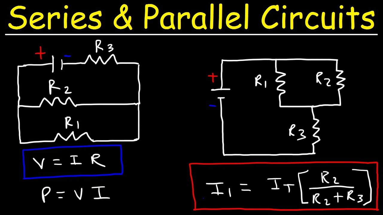
Circuit Diagram Of Resistors In Series And Parallel - Circuit Diagram In the previous tutorials we have learnt how to connect individual resistors together to form either a series resistor network or a parallel resistor network and we used ohms law to find the various currents and voltages across each resistor combination. A circuit with parallel connections has a smaller total resistance than the resistors connected in series. the individual currents are easily calculated from ohm’s law, since each resistor gets the full voltage.

Circuit Diagram Of Resistors In Series - Circuit Diagram
Circuit Diagram Of Resistors In Series - Circuit Diagram The addition of resistors can be achieved using any of the two methods i.e. series combination and parallel combination. in this article, we will learn about the arrangement of resistors in series and parallel combinations and others in detail. As an electronics student or as an engineering student, you should be able to solve simple and complex circuits. we will start with simple circuits and then in the end we will also solve some complex circuits as well. we will also solve circuits consisting series and parallel connections. The article discusses series parallel circuit, which are combinations of series and parallel resistor arrangements, explaining their analysis using equivalent resistance calculations and kirchhoff’s laws. Learn about resistors in series and parallel with easy explanations, diagrams, and real life applications. understand combinations and the basics of resistor networks in one place.

Series And Parallel Circuits Resistors Value - Circuit Diagram
Series And Parallel Circuits Resistors Value - Circuit Diagram The article discusses series parallel circuit, which are combinations of series and parallel resistor arrangements, explaining their analysis using equivalent resistance calculations and kirchhoff’s laws. Learn about resistors in series and parallel with easy explanations, diagrams, and real life applications. understand combinations and the basics of resistor networks in one place. Combine basic elements to sketch a complete circuit. identify series and parallel combination of resistors. compute equivalent resistance between two terminals. an electrical circuit can be seen as an interconnection of electrical elements in a closed path such that current can continuously flow. an example of a circuit is shown below. Resistors can be connected in series connection alone or in parallel connection alone. some resistor circuits are made from combination of series and parallel networks to develop more complex circuits. these circuits are generally known as mixed resistor circuits. The simplest combinations of resistors are series and parallel connections (figure 6.2.1). in a series circuit, the output current of the first resistor flows into the input of the second resistor; therefore, the current is the same in each resistor. In the set of experiments, the theoretical expressions used to calculate the total resistance in a combination of resistors will be tested experimentally. in addition, the expected distribution of the voltage and current to each resistor in a network will also be tested.

Circuit Diagram Series And Parallel
Circuit Diagram Series And Parallel Combine basic elements to sketch a complete circuit. identify series and parallel combination of resistors. compute equivalent resistance between two terminals. an electrical circuit can be seen as an interconnection of electrical elements in a closed path such that current can continuously flow. an example of a circuit is shown below. Resistors can be connected in series connection alone or in parallel connection alone. some resistor circuits are made from combination of series and parallel networks to develop more complex circuits. these circuits are generally known as mixed resistor circuits. The simplest combinations of resistors are series and parallel connections (figure 6.2.1). in a series circuit, the output current of the first resistor flows into the input of the second resistor; therefore, the current is the same in each resistor. In the set of experiments, the theoretical expressions used to calculate the total resistance in a combination of resistors will be tested experimentally. in addition, the expected distribution of the voltage and current to each resistor in a network will also be tested.

Circuit Diagram Resistors In Parallel Equivalent Resistance Of A Complex Circuit With Series And ...
Circuit Diagram Resistors In Parallel Equivalent Resistance Of A Complex Circuit With Series And ... The simplest combinations of resistors are series and parallel connections (figure 6.2.1). in a series circuit, the output current of the first resistor flows into the input of the second resistor; therefore, the current is the same in each resistor. In the set of experiments, the theoretical expressions used to calculate the total resistance in a combination of resistors will be tested experimentally. in addition, the expected distribution of the voltage and current to each resistor in a network will also be tested.

Parallel Circuit Series Circuit Diagram
Parallel Circuit Series Circuit Diagram
Resistors In Series and Parallel Circuits - Keeping It Simple!
Resistors In Series and Parallel Circuits - Keeping It Simple!
Related image with circuit diagram of resistors in series and parallel circuit diagram


Related image with circuit diagram of resistors in series and parallel circuit diagram


About "Circuit Diagram Of Resistors In Series And Parallel Circuit Diagram"
Comments are closed.