
RLC Series And Parallel | PDF | Electrical Impedance | Series And Parallel Circuits
RLC Series And Parallel | PDF | Electrical Impedance | Series And Parallel Circuits Match the proper values to the vector diagram of the values calculated for er, el, ec, el − ec, et, it, and the phase angle for the circuit shown. (be sure to place variables to the left and values to the right of the equals sign.). Rlc circuits can be connected in several ways, with series and parallel connections being the most common. unlike lc circuits, which oscillate indefinitely, the resistor in an rlc circuit causes the oscillations to decay more rapidly.

RLC Series-Parallel Circuit Analysis | PDF | Series And Parallel Circuits | Electrical Network
RLC Series-Parallel Circuit Analysis | PDF | Series And Parallel Circuits | Electrical Network However, one must understand the difference between series and parallel rlc circuits in order to optimize their effectiveness. series rlc circuits, where all components are connected in a single line, offer higher voltage capabilities than their parallel counterparts. Simplify an entire rlc network into a simple series or parallel equivalent comprised of complex impedances. utilize kvl, kcl and other techniques to find various voltages and currents in series parallel rlc networks driven by a single effective voltage or current source. When a resistor, inductor and capacitor are connected together in parallel or series combination, it operates as an oscillator circuit (known as rlc circuits) whose equations are given below in different scenarios as follow: when they are connected in parallel combination. total impedance of the circuit is; where. Read about series parallel r, l, and c (reactance and impedance—r, l, and c) in our free electronics textbook.
.jpg?strip=all?resize=650,400 "Comparing Series And Parallel Rlc Circuits")
Comparing Series And Parallel Rlc Circuits
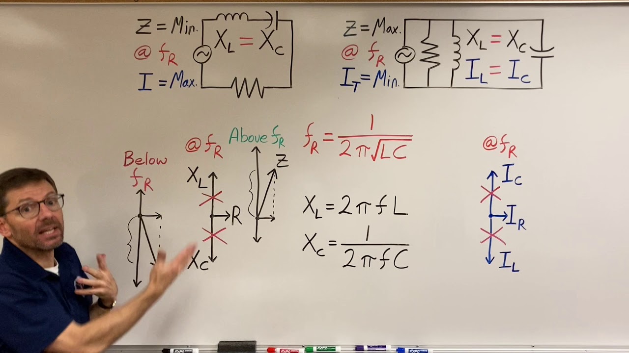
Comparing Series And Parallel Rlc Circuits When a resistor, inductor and capacitor are connected together in parallel or series combination, it operates as an oscillator circuit (known as rlc circuits) whose equations are given below in different scenarios as follow: when they are connected in parallel combination. total impedance of the circuit is; where. Read about series parallel r, l, and c (reactance and impedance—r, l, and c) in our free electronics textbook. In any ac circuit consisting of resistors, capacitors, and inductors, either in series or in parallel, a condition can happen in which the reactive power of the capacitors and of the inductors become equal. this condition is called resonance. Figure 222.9 this diagram shows how to determine the hypotenuse of the new right triangle which is the value of the total current of the circuit with the capacitor connected parallel to the rl circuit. The impedance and transient response of an rlc circuit differ between series and parallel configurations, enabling various applications in signal processing. moreover, understanding and appropriately adjusting the damping factor and q value in an rlc circuit is essential for designing high performance and energy efficient circuits. Get the full answer from quicktakes this content discusses the key differences between series and parallel rlc circuits in ac sinusoidal conditions, focusing on their configurations, impedance calculations, resonance behavior, power factor effects, and voltage and current relationships.

Comparing Series And Parallel Rlc Circuits
Comparing Series And Parallel Rlc Circuits In any ac circuit consisting of resistors, capacitors, and inductors, either in series or in parallel, a condition can happen in which the reactive power of the capacitors and of the inductors become equal. this condition is called resonance. Figure 222.9 this diagram shows how to determine the hypotenuse of the new right triangle which is the value of the total current of the circuit with the capacitor connected parallel to the rl circuit. The impedance and transient response of an rlc circuit differ between series and parallel configurations, enabling various applications in signal processing. moreover, understanding and appropriately adjusting the damping factor and q value in an rlc circuit is essential for designing high performance and energy efficient circuits. Get the full answer from quicktakes this content discusses the key differences between series and parallel rlc circuits in ac sinusoidal conditions, focusing on their configurations, impedance calculations, resonance behavior, power factor effects, and voltage and current relationships.

Comparing Series And Parallel Rlc Circuits - Circuit Diagram
Comparing Series And Parallel Rlc Circuits - Circuit Diagram The impedance and transient response of an rlc circuit differ between series and parallel configurations, enabling various applications in signal processing. moreover, understanding and appropriately adjusting the damping factor and q value in an rlc circuit is essential for designing high performance and energy efficient circuits. Get the full answer from quicktakes this content discusses the key differences between series and parallel rlc circuits in ac sinusoidal conditions, focusing on their configurations, impedance calculations, resonance behavior, power factor effects, and voltage and current relationships.

Lesson 8 Comparing Series And Parallel Rlc Circuits - Circuit Diagram
Lesson 8 Comparing Series And Parallel Rlc Circuits - Circuit Diagram
Comparing Series and Parallel RLC Circuits
Comparing Series and Parallel RLC Circuits
Related image with comparing series and parallel rlc circuits


.jpg?strip=all?resize=91,91 "Comparing Series And Parallel Rlc Circuits")


Related image with comparing series and parallel rlc circuits


About "Comparing Series And Parallel Rlc Circuits"
Comments are closed.