
RLC Series-Parallel Circuit Analysis | PDF | Series And Parallel Circuits | Electrical Network
RLC Series-Parallel Circuit Analysis | PDF | Series And Parallel Circuits | Electrical Network Rlc circuits can be connected in several ways, with series and parallel connections being the most common. unlike lc circuits, which oscillate indefinitely, the resistor in an rlc circuit causes the oscillations to decay more rapidly. These are the main differences between series, parallel, and rlc circuits. it is important to remember that no two circuits are the same, so be sure to research your intended application thoroughly before deciding which type of circuit will work best for you.

RLC Series And Parallel | PDF | Electrical Impedance | Series And Parallel Circuits
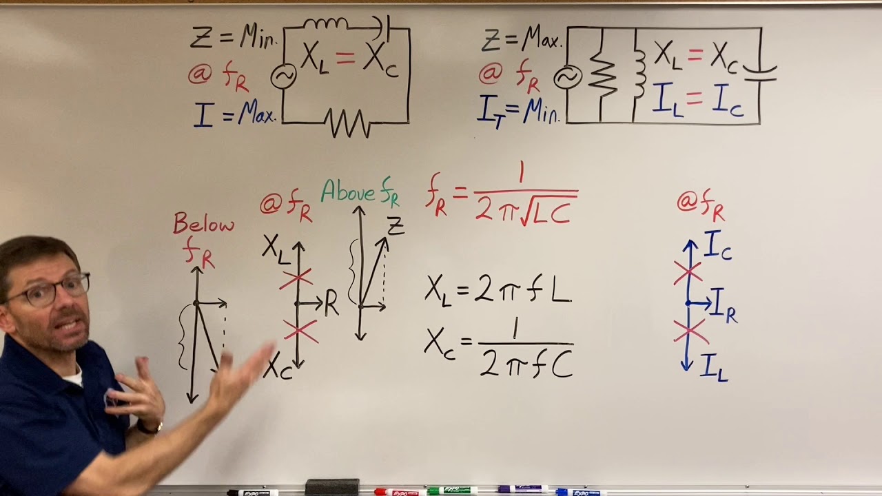
RLC Series And Parallel | PDF | Electrical Impedance | Series And Parallel Circuits An rlc circuit consists of a resistor, an inductor, and a capacitor. this electronic circuit can emphasize or eliminate signals of a specific frequency, making it effectively used in signal filtering and shaping. the impedance and transient response of an rlc circuit differ between series and parallel configurations, enabling various applications in signal processing. moreover, understanding. Simplify an entire rlc network into a simple series or parallel equivalent comprised of complex impedances. utilize kvl, kcl and other techniques to find various voltages and currents in series parallel rlc networks driven by a single effective voltage or current source. Get the full answer from quicktakes this content discusses the key differences between series and parallel rlc circuits in ac sinusoidal conditions, focusing on their configurations, impedance calculations, resonance behavior, power factor effects, and voltage and current relationships. There are generally two types of rlc circuit composition: series and parallel. the animation above demonstrates the operation of the lc circuit (rlc circuit without resistors).

Difference Between Series Parallel Rlc Circuit
Difference Between Series Parallel Rlc Circuit Get the full answer from quicktakes this content discusses the key differences between series and parallel rlc circuits in ac sinusoidal conditions, focusing on their configurations, impedance calculations, resonance behavior, power factor effects, and voltage and current relationships. There are generally two types of rlc circuit composition: series and parallel. the animation above demonstrates the operation of the lc circuit (rlc circuit without resistors). In parallel rlc circuit the resistor, inductor and capacitor are connected in parallel across a voltage supply. the parallel rlc circuit is exactly opposite to the series rlc circuit. the applied voltage remains the same across all components and the supply current gets divided. Learn the key differences between series and parallel circuits and how they apply to real world electrical systems. However, one must understand the difference between series and parallel rlc circuits in order to optimize their effectiveness. series rlc circuits, where all components are connected in a single line, offer higher voltage capabilities than their parallel counterparts. To understand the difference between series and parallel circuits, let us first define what a circuit is. an electric circuit is defined as a closed loop of conducting elements through which current can flow.

Difference Between Series And Parallel Rlc Circuits - Circuit Diagram
Difference Between Series And Parallel Rlc Circuits - Circuit Diagram In parallel rlc circuit the resistor, inductor and capacitor are connected in parallel across a voltage supply. the parallel rlc circuit is exactly opposite to the series rlc circuit. the applied voltage remains the same across all components and the supply current gets divided. Learn the key differences between series and parallel circuits and how they apply to real world electrical systems. However, one must understand the difference between series and parallel rlc circuits in order to optimize their effectiveness. series rlc circuits, where all components are connected in a single line, offer higher voltage capabilities than their parallel counterparts. To understand the difference between series and parallel circuits, let us first define what a circuit is. an electric circuit is defined as a closed loop of conducting elements through which current can flow.
Comparing Series and Parallel RLC Circuits
Comparing Series and Parallel RLC Circuits
Related image with difference between series parallel rlc circuit circuit diagram


Related image with difference between series parallel rlc circuit circuit diagram


About "Difference Between Series Parallel Rlc Circuit Circuit Diagram"
Comments are closed.