Mosfet %e4%b8%ad%e5%a4%a9%e9%bd%90%e6%b4%8b%e5%be%ae%e7%94%b5%e5%ad%90

All You Need To Know About E4 Gud Mosfet Datasheet And Specifications I want to make a mosfet model having the following parameters in ltspice: μncox = 100μa v2;vth = 0.5v, λ = 0 μ n c o x = 100 μ a v 2; v t h = 0.5 v, λ = 0 and to define w and l, where i can change it from one design to another. I am trying to understand the curves of a mosfet. sorry if the question is very basic. where the red point is is the saturation zone of the mosfet, therefore the source drain voltage must be 0v bec.

Very Simple Mosfet Design In Class A A B Diyaudio The intrinsic body diode is the p n junction between the body and the drain. in a discrete (standalone) mosfet, the source and body are usually tied together for convenience to make a three pin package. this means there's a diode between the source and drain: if the source voltage is always lower than the drain voltage, the diode stays off, and everything works as expected. this means you can. I am trying to understand this formula to find the transconductance of a mosfet transistor, but i am not getting the passage from the second to the third line. what happened there? thank you. It appears they also wear out much quicker. and solid state relays that i have found so far are generally very large compared to a mosfet or relay and drop a constant voltage up to 1v across them, which would be a big problem for high side switching of say 5v. This question is about enhanced n type mosfets. from what i understand, an inversion layer is formed underneath the insulating layer below the gate of the mosfet when a voltage is applied to the ga.

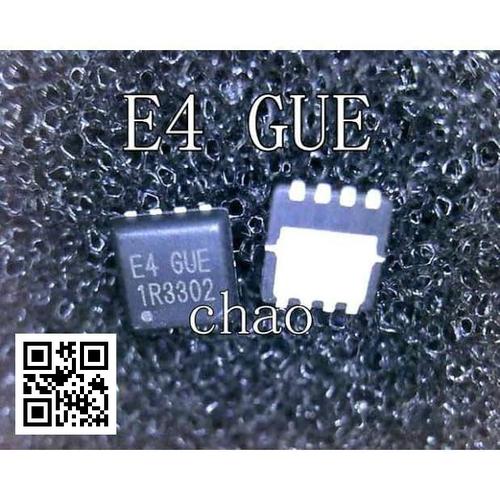
Jual Mosfet E4 Vuc E4 Gue E4 Gnb E4 Vub E4 Vne E4 Gub E4 Guc E4 Gnd Kota Tanjung Pinang Home It appears they also wear out much quicker. and solid state relays that i have found so far are generally very large compared to a mosfet or relay and drop a constant voltage up to 1v across them, which would be a big problem for high side switching of say 5v. This question is about enhanced n type mosfets. from what i understand, an inversion layer is formed underneath the insulating layer below the gate of the mosfet when a voltage is applied to the ga. Questions: 1) how to calculate the mosfet input resistor? 2) what are the factors affecting the mosfet input resistor calculation? 3) what will be the maximum, minimum resistor value possible and effect in the circuit if the resistor value is changed (increased or decreased) ? please let me know if any further info is required. I usually cheat and directly edit c:\program files\ltc\ltspice\lib\sym\standard.mos and add one more line with the .model statement. you need to add mfg= and vpk= manually. I am designing an h bridge with an n channel mosfet to control a 12v 1.35a dc motor. the h bridge will be controlled with the digital outputs of an arduino. i did some research and found that i n. 6 your equations are approximations to the capacitance seen between g d and g s of a mosfet in different regions of operation and they are derived based on the physical characteristics of the mosfet. keep in mind that the physical mosfet is a symmetric device.

E5 8f A4 E4 Bb A3 E4 B8 Ad E5 9b Bd E8 80 83 E5 8f A4 E5 Ad A6 Pdf Questions: 1) how to calculate the mosfet input resistor? 2) what are the factors affecting the mosfet input resistor calculation? 3) what will be the maximum, minimum resistor value possible and effect in the circuit if the resistor value is changed (increased or decreased) ? please let me know if any further info is required. I usually cheat and directly edit c:\program files\ltc\ltspice\lib\sym\standard.mos and add one more line with the .model statement. you need to add mfg= and vpk= manually. I am designing an h bridge with an n channel mosfet to control a 12v 1.35a dc motor. the h bridge will be controlled with the digital outputs of an arduino. i did some research and found that i n. 6 your equations are approximations to the capacitance seen between g d and g s of a mosfet in different regions of operation and they are derived based on the physical characteristics of the mosfet. keep in mind that the physical mosfet is a symmetric device.

048 F9 D5 E 66 B7 4189 B4 Cc 5 De3 Cf4 Bfe67 Hosted At Imgbb Imgbb I am designing an h bridge with an n channel mosfet to control a 12v 1.35a dc motor. the h bridge will be controlled with the digital outputs of an arduino. i did some research and found that i n. 6 your equations are approximations to the capacitance seen between g d and g s of a mosfet in different regions of operation and they are derived based on the physical characteristics of the mosfet. keep in mind that the physical mosfet is a symmetric device.

D5 A40 C9 D Ef8 E 4 D27 895 B 5 B0 Ac1 F4 F14 E Hosted At Imgbb Imgbb
Comments are closed.