Na 1 Introduction 2 Adc Dac Specifications 3 Driving Page 2 3 Created With Publitas Com

Na - 1-introduction-2-adc-dac-specifications-3-driving - Page 2-3 - Created With Publitas.com
Na - 1-introduction-2-adc-dac-specifications-3-driving - Page 2-3 - Created With Publitas.com Save this book to read 1 introduction 2 adc dac specifications 3 driving pdf ebook at our online library. get 1 introduction 2 adc dac specifications 3 driving. Identify various elements, processes, and parameters in telecommunications systems, and describe their functions, effects, and interrelationship. design procedure of am transmission & reception, analyze, measure, and evaluate the performance of a telecommunication system against given criteria.

Ch13 ADC, DAC And Sensor Interfacing | PDF | Analogue Electronics | Analog To Digital Converter
Ch13 ADC, DAC And Sensor Interfacing | PDF | Analogue Electronics | Analog To Digital Converter This tutorial outlines some important issues regarding dac interface circuitry including the voltage reference, analog output, data input, and clock driver. because adcs require references and clocks also, most of the concepts presented in this tutorial regarding these subjects apply equally to adcs. Lab description this lab will cover the design and simulation of a 10 bit digital to analog converter (dac) pre laboratory procedure. be sure to understand how the input voltage vin is related to b [9:0] and vout. The differential nonlinearity error shown in figure 5 (sometimes seen as simply differential linearity) is the difference between an actual step width (for an adc) or step height (for a dac) and the ideal value of 1 lsb. Folding and 2 step flash adc is different in dealing with the input signal. 2 step adc: direct conversion input signal, then residual signal; folding adc: first pre processing input signal, folding circuit used to generate folding number and residual signal; msb bits are obtained by corse adc conversion for the input data; simultaneously.

ADC Dan DAC | PDF
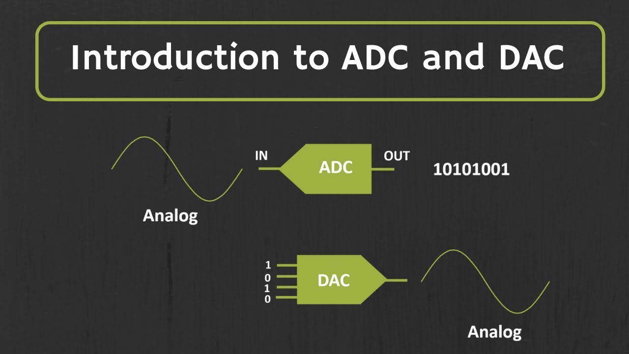
ADC Dan DAC | PDF The differential nonlinearity error shown in figure 5 (sometimes seen as simply differential linearity) is the difference between an actual step width (for an adc) or step height (for a dac) and the ideal value of 1 lsb. Folding and 2 step flash adc is different in dealing with the input signal. 2 step adc: direct conversion input signal, then residual signal; folding adc: first pre processing input signal, folding circuit used to generate folding number and residual signal; msb bits are obtained by corse adc conversion for the input data; simultaneously. * an adc (analog to digital converter) is used to convert an analog signal to the digital format. * the reverse conversion (from digital to analog) is also required. for example, music stored in a dvd in digital format must be converted to an analog voltage for playing out on a speaker. A ‘counting’ simplicity is slowness, simply output of a dac unknown analog the dac output the analog input conversion cycle and the dac that time provides output. The document summarizes key specifications for digital to analog converters (dacs) and analog to digital converters (adcs). for dacs, it describes resolution, linearity and associated errors, accuracy, monotonicity, settling time, stability, and sensitivity to factors like offset voltage, temperature, and time. Learn how to use adc for dc input voltage. familiarize yourself with the timing diagram. the ability to convert analog signals to digital and vice versa is very important in signal processing. the objective of an a/d converter is to determine the output digital word corresponding to an analog input signal.
 (English)")
Manual NAD MDC DAC 2 (page 2 Of 2) (English)
Manual NAD MDC DAC 2 (page 2 Of 2) (English) * an adc (analog to digital converter) is used to convert an analog signal to the digital format. * the reverse conversion (from digital to analog) is also required. for example, music stored in a dvd in digital format must be converted to an analog voltage for playing out on a speaker. A ‘counting’ simplicity is slowness, simply output of a dac unknown analog the dac output the analog input conversion cycle and the dac that time provides output. The document summarizes key specifications for digital to analog converters (dacs) and analog to digital converters (adcs). for dacs, it describes resolution, linearity and associated errors, accuracy, monotonicity, settling time, stability, and sensitivity to factors like offset voltage, temperature, and time. Learn how to use adc for dc input voltage. familiarize yourself with the timing diagram. the ability to convert analog signals to digital and vice versa is very important in signal processing. the objective of an a/d converter is to determine the output digital word corresponding to an analog input signal.
Introduction to ADC and DAC
Introduction to ADC and DAC
Related image with na 1 introduction 2 adc dac specifications 3 driving page 2 3 created with publitas com


 (English)")
 E(2) U(z) C(2) DAC G(s) ADC FIGURE P3.11 Block | Chegg.com")


Related image with na 1 introduction 2 adc dac specifications 3 driving page 2 3 created with publitas com


About "Na 1 Introduction 2 Adc Dac Specifications 3 Driving Page 2 3 Created With Publitas Com"
Comments are closed.