
RLC Series-Parallel Circuit Analysis | PDF | Series And Parallel Circuits | Electrical Network
RLC Series-Parallel Circuit Analysis | PDF | Series And Parallel Circuits | Electrical Network Rlc circuits can be connected in several ways, with series and parallel connections being the most common. unlike lc circuits, which oscillate indefinitely, the resistor in an rlc circuit causes the oscillations to decay more rapidly. When a resistor, inductor and capacitor are connected together in parallel or series combination, it operates as an oscillator circuit (known as rlc circuits) whose equations are given below in different scenarios as follow:.

RLC Series And Parallel | PDF | Electrical Impedance | Series And Parallel Circuits
RLC Series And Parallel | PDF | Electrical Impedance | Series And Parallel Circuits Simplify an entire rlc network into a simple series or parallel equivalent comprised of complex impedances. utilize kvl, kcl and other techniques to find various voltages and currents in series parallel rlc networks driven by a single effective voltage or current source. To help simplify these circuit problems, we’ve put together an article exploring the basics of series and parallel circuit problems and providing helpful pdfs that contain solutions for each type. Example series parallel r, l, and c circuit. the first order of business, as usual, is to determine values of impedance (z) for all components based on the frequency of the ac power source. An rlc circuit consists of a resistor, an inductor, and a capacitor. this electronic circuit can emphasize or eliminate signals of a specific frequency, making it effectively used in signal filtering and shaping. the impedance and transient response of an rlc circuit differ between series and parallel configurations, enabling various applications in signal processing. moreover, understanding.

Rlc Series Parallel Circuit
Rlc Series Parallel Circuit Example series parallel r, l, and c circuit. the first order of business, as usual, is to determine values of impedance (z) for all components based on the frequency of the ac power source. An rlc circuit consists of a resistor, an inductor, and a capacitor. this electronic circuit can emphasize or eliminate signals of a specific frequency, making it effectively used in signal filtering and shaping. the impedance and transient response of an rlc circuit differ between series and parallel configurations, enabling various applications in signal processing. moreover, understanding. Figure 222.9 this diagram shows how to determine the hypotenuse of the new right triangle which is the value of the total current of the circuit with the capacitor connected parallel to the rl circuit. There are generally two types of rlc circuit composition: series and parallel. the animation above demonstrates the operation of the lc circuit (rlc circuit without resistors). Given the infinite variety of series parallel configurations, there are myriad ways of solving any given circuit for a particular current or voltage. many solution paths exist. this is good, because while you might not see a particular path, there are others that will also provide correct results. Being a series parallel combination circuit, we must reduce it to a total impedance in more than one step. the first step is to combine l and c 2 as a series combination of impedances, by adding their impedances together.

Rlc Series Parallel Circuit - Circuit Diagram
Rlc Series Parallel Circuit - Circuit Diagram Figure 222.9 this diagram shows how to determine the hypotenuse of the new right triangle which is the value of the total current of the circuit with the capacitor connected parallel to the rl circuit. There are generally two types of rlc circuit composition: series and parallel. the animation above demonstrates the operation of the lc circuit (rlc circuit without resistors). Given the infinite variety of series parallel configurations, there are myriad ways of solving any given circuit for a particular current or voltage. many solution paths exist. this is good, because while you might not see a particular path, there are others that will also provide correct results. Being a series parallel combination circuit, we must reduce it to a total impedance in more than one step. the first step is to combine l and c 2 as a series combination of impedances, by adding their impedances together.
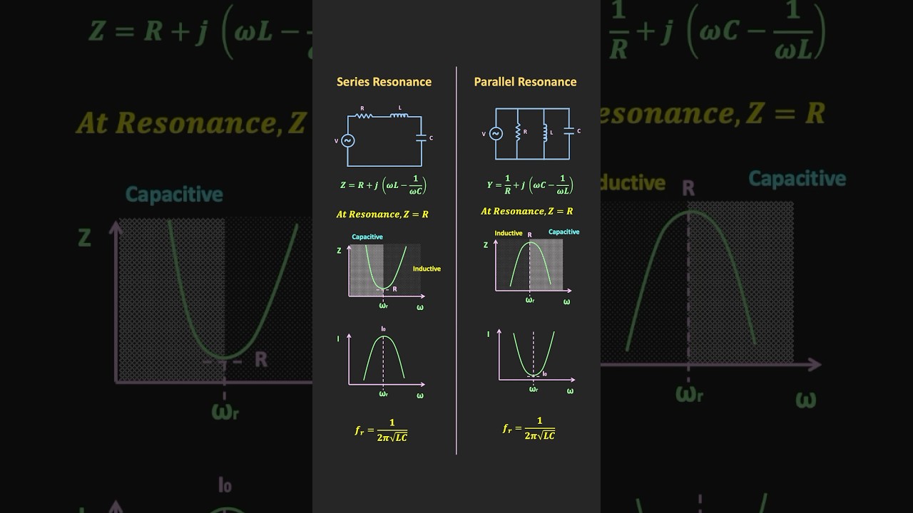
Series Resonance Vs Parallel Resonance #resonance
Series Resonance Vs Parallel Resonance #resonance
Related image with rlc series parallel circuit


... | Download Scientific ...")


Related image with rlc series parallel circuit


About "Rlc Series Parallel Circuit"
Comments are closed.