
Solved For The Following Circuit, Assume That V_1 =1V And | Chegg.com
Solved For The Following Circuit, Assume That V_1 =1V And | Chegg.com There are 3 steps to solve this one. 1. given the following circuit, calculate the current through resistor r, (i3 = ?). please use the practical model for the diode. 2. following figure shows a full wave rectifier circuit that uses a center tapped transformer. Consider a silicon sample maintained at 300k under equilibrium conditions, uniformly doped with 1*1016 cm 3 phosphorus atoms. the surface region of the sample is additionally doped uniformly with 5*1016 cm 3 boron atoms, to a depth of 1 microm, as shown in the figure below.

Solved 1. Given The Following Circuit, Assume That | Chegg.com
Solved 1. Given The Following Circuit, Assume That | Chegg.com Problem 13 sketch the steady state output voltage v0 versus time for each circuit with the input voltage shown in the following figure. assume vᵞ=0 v and assume the rc time constant is large. We go through a similar process to problem 1, where we assume saturation for the pmos transistor and plug in the saturation regionidequation into the kvl gate source loop equation. At this time, the current through the inductor forces that part of the circuit to act like a current source and the capacitor acts like a voltage source. this produces the circuit shown below. Find step by step solutions and answers to exercise 64 from fundamentals of electric circuits 9781260570793, as well as thousands of textbooks so you can move forward with confidence.

Solved Given The Following Circuit, As Shown Below: Assume | Chegg.com
Solved Given The Following Circuit, As Shown Below: Assume | Chegg.com At this time, the current through the inductor forces that part of the circuit to act like a current source and the capacitor acts like a voltage source. this produces the circuit shown below. Find step by step solutions and answers to exercise 64 from fundamentals of electric circuits 9781260570793, as well as thousands of textbooks so you can move forward with confidence. For the circuit shown in the figure, calculate the following. (assume e=8.22v and r=6.24Ω.) (a) the current in the 2.00 Ω resistor (enter the magnitude.) a (b) the potential difference between points a and b,Δv=vb vs v. Part a consider the circuit shown in (figure 1). suppose that i, = 8a. find 21 . express your answer to three significant figures and include the appropriate units. 21 = value units submit request answer part b find v. express your answer to three significant figures and include the appropriate units. ? v = value show more show more. There are 3 steps to solve this one. consider the circuit shown below. not the question you’re looking for? post any question and get expert help quickly. answer to consider the circuit shown below. Our expert help has broken down your problem into an easy to learn solution you can count on. here’s the best way to solve it.

Solved Consider The Following Circuit: Assume The Following | Chegg.com
Solved Consider The Following Circuit: Assume The Following | Chegg.com For the circuit shown in the figure, calculate the following. (assume e=8.22v and r=6.24Ω.) (a) the current in the 2.00 Ω resistor (enter the magnitude.) a (b) the potential difference between points a and b,Δv=vb vs v. Part a consider the circuit shown in (figure 1). suppose that i, = 8a. find 21 . express your answer to three significant figures and include the appropriate units. 21 = value units submit request answer part b find v. express your answer to three significant figures and include the appropriate units. ? v = value show more show more. There are 3 steps to solve this one. consider the circuit shown below. not the question you’re looking for? post any question and get expert help quickly. answer to consider the circuit shown below. Our expert help has broken down your problem into an easy to learn solution you can count on. here’s the best way to solve it.

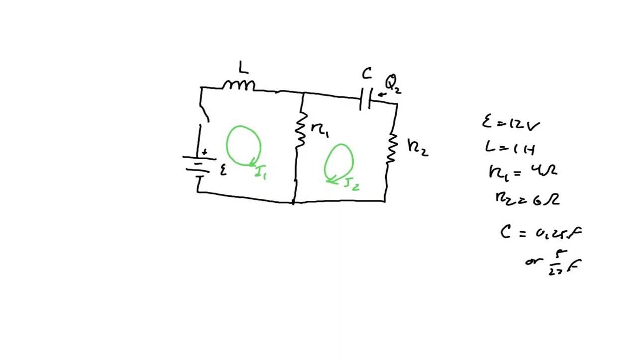
Solved Consider The Following Circuit: Assume The Following | Chegg.com
Solved Consider The Following Circuit: Assume The Following | Chegg.com There are 3 steps to solve this one. consider the circuit shown below. not the question you’re looking for? post any question and get expert help quickly. answer to consider the circuit shown below. Our expert help has broken down your problem into an easy to learn solution you can count on. here’s the best way to solve it.

Solved In The Circuit Shown In The Given Figure Assum - Vrogue.co
Solved In The Circuit Shown In The Given Figure Assum - Vrogue.co
https://www.chegg.com/homework-help/questions-and-answers/let-1-t-2-t-currents-network-figure–assu…
https://www.chegg.com/homework-help/questions-and-answers/let-1-t-2-t-currents-network-figure–assu…
Related image with solved 1 given the following circuit assume that chegg com


 Assume The | Chegg.com")
 Assume The | Chegg.com")
 Assume The | Chegg.com")
 Assume The | Chegg.com")
 Assume The | Chegg.com")
Related image with solved 1 given the following circuit assume that chegg com


About "Solved 1 Given The Following Circuit Assume That Chegg Com"
Comments are closed.