
Solved 17. The Block Diagram Of 7483 4-bit Full Adder Is | Chegg.com
Solved 17. The Block Diagram Of 7483 4-bit Full Adder Is | Chegg.com 17. the block diagram of 7483 4 bit full adder is given below. draw the block diagram of an 8 bit full adder. label the pins as a1 a8, b1 b8, Σ1 Σ8. draw your diagram below here:. The adder block itself is composed of three full adder cells and one half adder cell, which are all interconnected by nor, xor, and, and or gates. this 7483 full adder circuit diagram is quite versatile, allowing for a wide range of numerical operations.

7483 4-bit Binary Full Adder IC 74LS83, 41% OFF
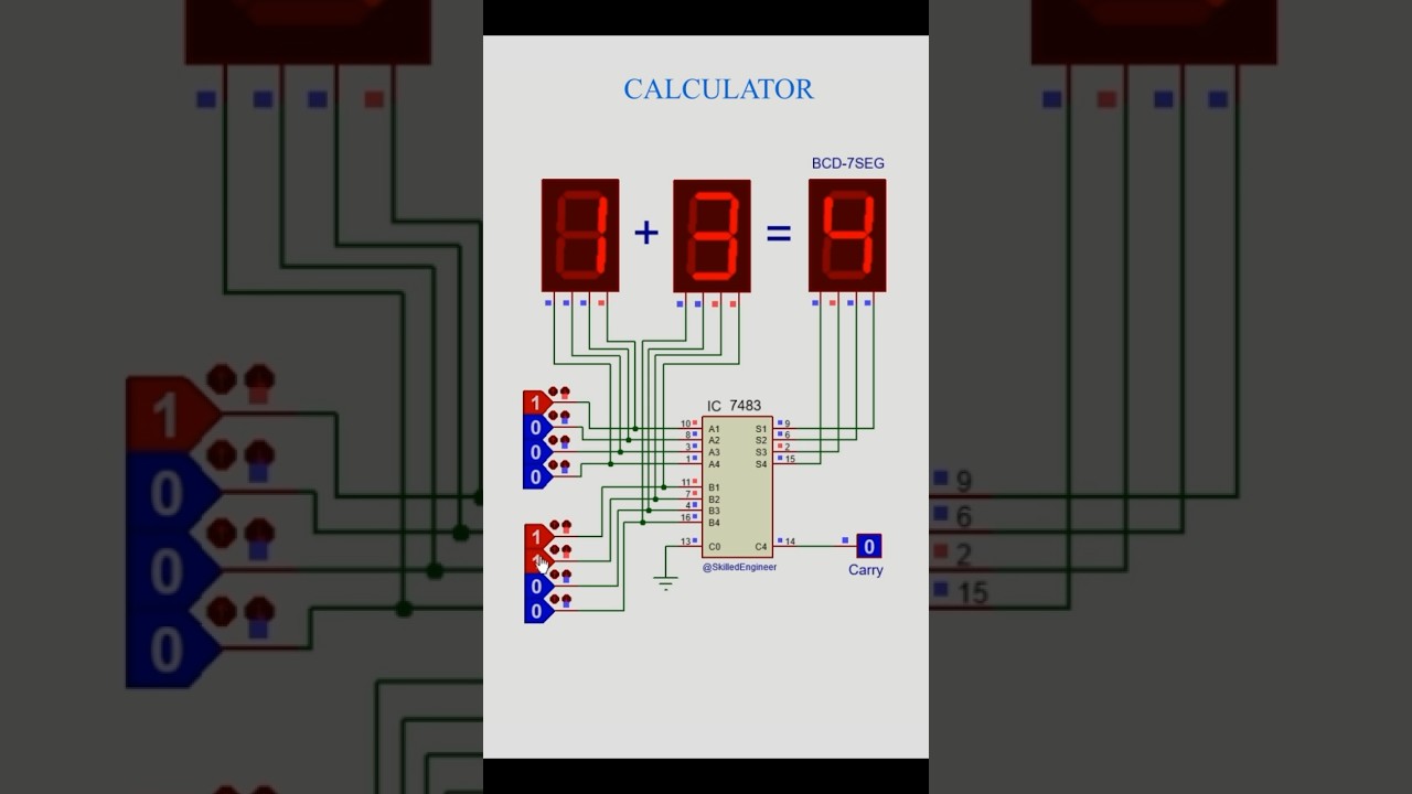
7483 4-bit Binary Full Adder IC 74LS83, 41% OFF A circuit diagram for a 4 bit binary adder using an ic 7483 can help you design complex digital systems with greater accuracy and efficiency. with the right setup, this type of circuit can perform addition of two binary numbers quickly and accurately. In conclusion, a 4 bit binary adder using ic 7483 is a powerful and useful tool for electrical engineers. it allows two 4 bit binary numbers to be added together quickly and accurately, and the circuit diagram for this type of adder provides a concise overview of how it works. Describe with the aid of a diagram how you would use it to make a 4 bit binary adder subtracter. use the block symbol for the ic above plus any additional circuitry to draw the binary adder that you have designed. For all the combinations of the 4 bit inputs a ( \ (a 3 a 2 a 1 a 0\)),b ( \ (b 3 b 2 b 1 b 0\)) verify that the leds are on or not. note: red button symbolize as low (l), green button symbolize as high (h).

Solved The IC 7483 Is A 4-bit Full Binary Adder Adding | Chegg.com
Solved The IC 7483 Is A 4-bit Full Binary Adder Adding | Chegg.com Describe with the aid of a diagram how you would use it to make a 4 bit binary adder subtracter. use the block symbol for the ic above plus any additional circuitry to draw the binary adder that you have designed. For all the combinations of the 4 bit inputs a ( \ (a 3 a 2 a 1 a 0\)),b ( \ (b 3 b 2 b 1 b 0\)) verify that the leds are on or not. note: red button symbolize as low (l), green button symbolize as high (h). The 7483 circuit diagram full adder is an indispensable part of many digital designs. it not only simplifies arithmetic operations, but also provides a powerful tool for creating more complex solutions. By understanding how the 7483 chip works and how it is used to create a 4 bit binary adder, you can now begin to construct your own circuit diagram for this type of circuit. This lab manual has provided an overview of how to build a 4 bit adder using the ic 7483. by following the instructions in this manual, you will be able to quickly and accurately add two binary values. The circuit diagram for a 4 bit binary adder using ic 7483 is a crucial element of digital circuitry. this type of adder uses an integrated circuit (ic) to add two binary numbers, resulting in a sum output.

Solved - Design A 8-bit Full Adder. Draw The Block Diagram. | Chegg.com
Solved - Design A 8-bit Full Adder. Draw The Block Diagram. | Chegg.com The 7483 circuit diagram full adder is an indispensable part of many digital designs. it not only simplifies arithmetic operations, but also provides a powerful tool for creating more complex solutions. By understanding how the 7483 chip works and how it is used to create a 4 bit binary adder, you can now begin to construct your own circuit diagram for this type of circuit. This lab manual has provided an overview of how to build a 4 bit adder using the ic 7483. by following the instructions in this manual, you will be able to quickly and accurately add two binary values. The circuit diagram for a 4 bit binary adder using ic 7483 is a crucial element of digital circuitry. this type of adder uses an integrated circuit (ic) to add two binary numbers, resulting in a sum output.

7483 4-bit Binary Full Adder - Ekostra Elecronics Store
7483 4-bit Binary Full Adder - Ekostra Elecronics Store This lab manual has provided an overview of how to build a 4 bit adder using the ic 7483. by following the instructions in this manual, you will be able to quickly and accurately add two binary values. The circuit diagram for a 4 bit binary adder using ic 7483 is a crucial element of digital circuitry. this type of adder uses an integrated circuit (ic) to add two binary numbers, resulting in a sum output.
4bit Full Adder IC 7483 #electronics #digital
4bit Full Adder IC 7483 #electronics #digital
Related image with solved 17 the block diagram of 7483 4 bit full adder is chegg com


Related image with solved 17 the block diagram of 7483 4 bit full adder is chegg com


About "Solved 17 The Block Diagram Of 7483 4 Bit Full Adder Is Chegg Com"
Comments are closed.