
Solved 2. Consider The Circuit Shown In Figure 2 Below. | Chegg.com
Solved 2. Consider The Circuit Shown In Figure 2 Below. | Chegg.com Question: 4a consider the circuit shown in figure 2. assume that all diodes are identical and equal to the diode shown in fig. 1., and that they have an exponential i v characteristic. 2. consider a device whose i v characteristic is shown below: a. find “incremental resistance” of the device in all regions of operation. b. sketch the incremental model of the circuit shown below. c. determine the region (a, b, c, or d) in which the device should be operated to maximize incremental gain, a v = v out v in .
. (Figure 2) | Chegg.com")
Solved Consider The Circuits Shown In (Figure 1). (Figure 2) | Chegg.com
Solved Consider The Circuits Shown In (Figure 1). (Figure 2) | Chegg.com Determine the power supplied by each voltage source in the circuit of figure p 3.2 6. the 2 v voltage source supplies 2 mw and the 3 v voltage source supplies –6 mw. Explanation the circuit shown in the figure can be solved using ohm's law and the formula for calculating the total resistance in a series circuit. to find the current (i) flowing through the circuit, we can use the formula i = v/r, where v is the voltage and r is the total resistance. Consider the circuit shown in (figure 1). assume i = 0.88 a. what is the value of resistor r?. Consider the instrumentation amplifier circuit of fig. 2.20(a). if the op amps are ideal except that their outputs saturate at ±14 v in the manner shown in fig. 1.13, find the maximum allowed input common mode signal for the case r1 = 1 kΩ and r2 = 100 kΩ.
. (Figure | Chegg.com")
Solved Consider The Circuits Shown In (Figure 1). (Figure | Chegg.com
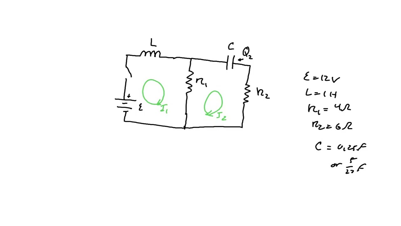
Solved Consider The Circuits Shown In (Figure 1). (Figure | Chegg.com Consider the circuit shown in (figure 1). assume i = 0.88 a. what is the value of resistor r?. Consider the instrumentation amplifier circuit of fig. 2.20(a). if the op amps are ideal except that their outputs saturate at ±14 v in the manner shown in fig. 1.13, find the maximum allowed input common mode signal for the case r1 = 1 kΩ and r2 = 100 kΩ. Consider the circuit shown in the figure below. (assume r1 = 12.0 Ω, r2 = 3.45 Ω, and v = 6.45 v.) (g) subtracting the result of part (f) from the battery voltage, find the voltage across the 3.00 Ω resistor. Consider the circuit shown in the gure below. assume vt=25mv, vin=10v, vin=0.1v. using constant voltage model for the diode with vd0=0.7v, compute diode current, id0, and its incremental resistance, rd. Kirchhoff's current law (kcl) states that the sum of currents entering a node is equal to the sum of currents leaving the node. kirchhoff's voltage law (kvl) states that the sum of voltages around a closed loop is zero. here's a step by step solution to analyze the given circuit. Our expert help has broken down your problem into an easy to learn solution you can count on. question: 2. consider the circuit shown in figure 2. assume that the switch s is open for t<0 and he capacitor c is initially charged so that the initial voltage cq (0)=e0 appears on the capacitor.
. Assume E = | Chegg.com")
Consider The Circuit Shown In (Figure 1). Assume E = | Chegg.com
Consider The Circuit Shown In (Figure 1). Assume E = | Chegg.com Consider the circuit shown in the figure below. (assume r1 = 12.0 Ω, r2 = 3.45 Ω, and v = 6.45 v.) (g) subtracting the result of part (f) from the battery voltage, find the voltage across the 3.00 Ω resistor. Consider the circuit shown in the gure below. assume vt=25mv, vin=10v, vin=0.1v. using constant voltage model for the diode with vd0=0.7v, compute diode current, id0, and its incremental resistance, rd. Kirchhoff's current law (kcl) states that the sum of currents entering a node is equal to the sum of currents leaving the node. kirchhoff's voltage law (kvl) states that the sum of voltages around a closed loop is zero. here's a step by step solution to analyze the given circuit. Our expert help has broken down your problem into an easy to learn solution you can count on. question: 2. consider the circuit shown in figure 2. assume that the switch s is open for t<0 and he capacitor c is initially charged so that the initial voltage cq (0)=e0 appears on the capacitor.

Solved Problem 2.12 Part A Consider The Circuit Shown In | Chegg.com
Solved Problem 2.12 Part A Consider The Circuit Shown In | Chegg.com Kirchhoff's current law (kcl) states that the sum of currents entering a node is equal to the sum of currents leaving the node. kirchhoff's voltage law (kvl) states that the sum of voltages around a closed loop is zero. here's a step by step solution to analyze the given circuit. Our expert help has broken down your problem into an easy to learn solution you can count on. question: 2. consider the circuit shown in figure 2. assume that the switch s is open for t<0 and he capacitor c is initially charged so that the initial voltage cq (0)=e0 appears on the capacitor.

Solved Consider The Circuit Shown In Figure 2. Figure 2. | Chegg.com
Solved Consider The Circuit Shown In Figure 2. Figure 2. | Chegg.com
https://www.chegg.com/homework-help/questions-and-answers/let-1-t-2-t-currents-network-figure–assu…
https://www.chegg.com/homework-help/questions-and-answers/let-1-t-2-t-currents-network-figure–assu…
Related image with solved 2 consider the circuit shown in figure 2 assume chegg com

. (Figure 2) | Chegg.com")
. (Figure | Chegg.com")
. Assume E = | Chegg.com")


. Suppose | Chegg.com")
, (Figure | Chegg.com")
 Assume | Chegg.com")
Related image with solved 2 consider the circuit shown in figure 2 assume chegg com


About "Solved 2 Consider The Circuit Shown In Figure 2 Assume Chegg Com"
Comments are closed.