
Solved 2. Given The Circuit Shown In Figure 2, Perform The | Chegg.com
Solved 2. Given The Circuit Shown In Figure 2, Perform The | Chegg.com A) using a simulator of your choice, reproduce the circuit in figure 2. make a side note of the voltages, currents and power dissipations indicated by a simulation run. Determine the power supplied by each voltage source in the circuit of figure p 3.2 6. the 2 v voltage source supplies 2 mw and the 3 v voltage source supplies –6 mw.

Solved 2. Consider The Circuit Shown In Figure 2 Below. | Chegg.com
Solved 2. Consider The Circuit Shown In Figure 2 Below. | Chegg.com It is important that circuit designers gain physical insight into the working of the circuit with speedy analysis. later, if needed, more elaborate analysis can be done with commercial software such as spice. Element a. p 2.2 5 the circuit shown in figure p 2.2 5 consists of a current source, a resistor, and element a. Use two jk ip ops and a minimal and or not network to implement the machine. Fig. 2 problem 3 in the circuit of fig. 3, find the value of the coupling coefficient k that makes the 10 resistor dissipate a 1.28 kw. for this value of k, find the energy stored in the coupled coils at t = 1.5 s.

Solved Consider The Circuit Shown In Figure 2. Figure 2. | Chegg.com
Solved Consider The Circuit Shown In Figure 2. Figure 2. | Chegg.com Use two jk ip ops and a minimal and or not network to implement the machine. Fig. 2 problem 3 in the circuit of fig. 3, find the value of the coupling coefficient k that makes the 10 resistor dissipate a 1.28 kw. for this value of k, find the energy stored in the coupled coils at t = 1.5 s. For a given passive linear network, the thevenin equivalent circuit series resistance and norton equivalent circuit parallel resistance are respectively rth and rn. Problems section 2.2 ohm’s law 2.1 design a problem, complete with a solution, to help students to better understand ohm’s law. use at least two resistors and one voltage source. hint, you could use both resistors at once or one at a time, it is up to you. At this time, the current through the inductor forces that part of the circuit to act like a current source and the capacitor acts like a voltage source. this produces the circuit shown below. Look up the mathematical relationship for finding total resistance in a parallel circuit. write the formula below and show that your data fits the relationship by plugging in your values for resistance.
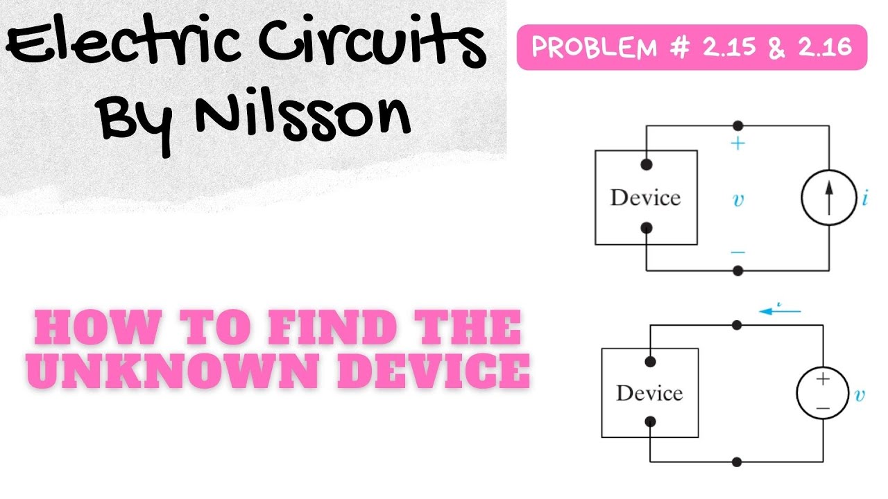
2.15 & 2.16 : Solution – Electric Circuits by Nilsson | Chapter 2: Exercise Solution
2.15 & 2.16 : Solution – Electric Circuits by Nilsson | Chapter 2: Exercise Solution
Related image with solved 2 given the circuit shown in figure 2 perform the chegg com


: Given The Circuit Shown In Figure. 2, | Chegg.com")
: Given The Circuit Shown In Figure. 2, | Chegg.com")


Related image with solved 2 given the circuit shown in figure 2 perform the chegg com

 the current in the 2.00-Ω resistor and (b) the po")


About "Solved 2 Given The Circuit Shown In Figure 2 Perform The Chegg Com"
Comments are closed.