
Solved 6. Consider The Circuits Shown In Fig. 6. Fig. 6 | Chegg.com
Solved 6. Consider The Circuits Shown In Fig. 6. Fig. 6 | Chegg.com Our expert help has broken down your problem into an easy to learn solution you can count on. question: 6. consider the circuits shown in fig. 6. fig. 6 determine: there are 3 steps to solve this one. refer to the circuit shown in the figure in the question. the arms − j 5 Ω and j 4 Ω are in parallel. their equiv 6. Question: consider the circuit shown in fig. 6.22 (a), which is redrawn in fig. 6.22 (b) to remind the reader of the convention employed throughout this book for indicating connections to.

Solved 6. Consider The Circuits Shown In Fig. 6. Fig. 6 | Chegg.com
Solved 6. Consider The Circuits Shown In Fig. 6. Fig. 6 | Chegg.com Problem 6 6. for the circuit shown in figure p6 6, find vc (t) and ic (t) for tz 0 . the switches have been in answered step by step solved by verified expert university of connecticut • ece • ece 2001 question answeredstep by step asked by drgoldfishperson242 engineering & technology electrical engineering ece 2001. Q6. consider the circuit shown in fig. 6. (a) find the resistance req=v1/i1. (b) use voltage division to find v in terms of vg. (c) find the voltage v2 in terms of the applied voltage v1. figure 6: circuit diagram. views: 5,581 students updated on: aug 3, 2024. *6.76 consider the circuit shown in figure p6.76 with transistor parameters β = 120 and v a = ∞. (a) determine the small signal parameters g m , rπ , and r o for both transistors. The question involves analyzing a transistor circuit to find dc terminal voltages, overall beta, small signal emitter resistance, total input resistance, and overall current gain. each item is derived using fundamental principles of transistor operation and circuit analysis.

Solved 6. Consider The Circuits Shown In Fig. 6. Fig. 6 | Chegg.com
Solved 6. Consider The Circuits Shown In Fig. 6. Fig. 6 | Chegg.com *6.76 consider the circuit shown in figure p6.76 with transistor parameters β = 120 and v a = ∞. (a) determine the small signal parameters g m , rπ , and r o for both transistors. The question involves analyzing a transistor circuit to find dc terminal voltages, overall beta, small signal emitter resistance, total input resistance, and overall current gain. each item is derived using fundamental principles of transistor operation and circuit analysis. The resistor in the circuit introduces a voltage drop that helps counteract normal variations in current, thereby enhancing the stability and linearity of the circuit’s operation. Your solution’s ready to go! our expert help has broken down your problem into an easy to learn solution you can count on. see answer question: 6. consider the circuits shown in fig. 6. fig. 6 determine: is= a i1= a i2= a v0= v show transcribed image text. To solve this problem, we need to analyze the circuit in two scenarios: with resistor r open circuited and with r connected. we will use the given values for v be and v d as 0.7 v and consider two cases for the transistor current gain β: β = ∞ and β = 100. At this time, the current through the inductor forces that part of the circuit to act like a current source and the capacitor acts like a voltage source. this produces the circuit shown below.

Solved Example 6.4 Consider He Circuit Shown In Fig. | Chegg.com
Solved Example 6.4 Consider He Circuit Shown In Fig. | Chegg.com The resistor in the circuit introduces a voltage drop that helps counteract normal variations in current, thereby enhancing the stability and linearity of the circuit’s operation. Your solution’s ready to go! our expert help has broken down your problem into an easy to learn solution you can count on. see answer question: 6. consider the circuits shown in fig. 6. fig. 6 determine: is= a i1= a i2= a v0= v show transcribed image text. To solve this problem, we need to analyze the circuit in two scenarios: with resistor r open circuited and with r connected. we will use the given values for v be and v d as 0.7 v and consider two cases for the transistor current gain β: β = ∞ and β = 100. At this time, the current through the inductor forces that part of the circuit to act like a current source and the capacitor acts like a voltage source. this produces the circuit shown below.

Solved Consider The Circuits Shown In Figure 1 Figure - Vrogue.co
Solved Consider The Circuits Shown In Figure 1 Figure - Vrogue.co To solve this problem, we need to analyze the circuit in two scenarios: with resistor r open circuited and with r connected. we will use the given values for v be and v d as 0.7 v and consider two cases for the transistor current gain β: β = ∞ and β = 100. At this time, the current through the inductor forces that part of the circuit to act like a current source and the capacitor acts like a voltage source. this produces the circuit shown below.

Solved Example 6.4 Consider He Circuit Shown In Fig. | Chegg.com
Solved Example 6.4 Consider He Circuit Shown In Fig. | Chegg.com
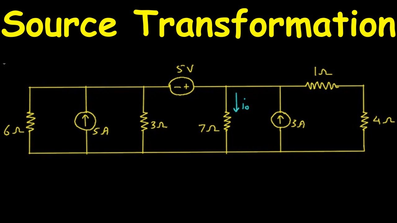
Source Transformation | Electric Circuits | Practice Problem 4.6 | Electrical Engineering
Source Transformation | Electric Circuits | Practice Problem 4.6 | Electrical Engineering
Related image with solved 6 consider the circuits shown in fig 6 fig 6 chegg com


, | Chegg.com")
, | Chegg.com")

. | Chegg.com")


Related image with solved 6 consider the circuits shown in fig 6 fig 6 chegg com


About "Solved 6 Consider The Circuits Shown In Fig 6 Fig 6 Chegg Com"
Comments are closed.