
Solved Consider The Circuit Shown In The Figure Below - Vrogue.co
Solved Consider The Circuit Shown In The Figure Below - Vrogue.co Your solution’s ready to go! our expert help has broken down your problem into an easy to learn solution you can count on. see answer. To approach this circuit problem, we first need to identify the values of the resistors and their configuration (series or parallel). given that the total voltage provided by the battery is e = 11v, we can analyze each part systematically.

Solved Consider The Circuit Shown In Figure 1 Assume - Vrogue.co
Solved Consider The Circuit Shown In Figure 1 Assume - Vrogue.co In an electric circuit, the maximum power transferred to load resistance is 2Ω is 50 w. if now, the load resistance is changed to 8Ω, what will be the power transferred to the load?. Consider the circuit shown above right. here, you will use the following nmos and pmos models. you can import them into ltspice a. determine w2 such that an input dc level of 0.75 v yields an output dc level of 1 v. what is the low frequency voltage gain under these conditions?. Simplify first order circuits with solved problems to excel in your exams and grasp key concepts easily. Analysis: for superposition we will have to suppress the sources. begin by suppressing e1 and e2 by replacing them with a short circuit ( i.e., a wire).

Solved Consider The Circuit Shown Below. The Switch In The | Chegg.com
Solved Consider The Circuit Shown Below. The Switch In The | Chegg.com Simplify first order circuits with solved problems to excel in your exams and grasp key concepts easily. Analysis: for superposition we will have to suppress the sources. begin by suppressing e1 and e2 by replacing them with a short circuit ( i.e., a wire). Solve the circuit of figure 2 using mesh analysis. note that the unknown mesh currents i1, i2, and i3 have already been defined for you, so you should not change the definitions already given in figure 2 above; expect zero credit for not following instructions. To get the voltage across r1 and the current in r1 in the circuit depicted in the picture, we must apply **ohm's **and kirchhoff's laws. according to ohm's law, the voltage across a resistor equals the current through it multiplied by its resistance. The purpose of this exercise is to help you recognize the features of a circuit that are not necessary for a solution. hint: write the equations to completely solve the circuit, then cross out the ones that aren't needed. Consider the circuit shown in (figure 1). what is the potential difference across the 10Ω resistor? what is the potential difference across the 20Ω resistor?.
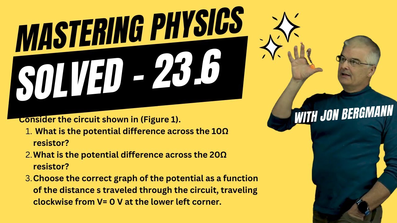
Mastering Physics 23.6 Solved! Consider the circuit shown in (Figure 1). What is the potential
Mastering Physics 23.6 Solved! Consider the circuit shown in (Figure 1). What is the potential
Related image with solved consider the circuit shown above right here you chegg com


Related image with solved consider the circuit shown above right here you chegg com
. What is the potential")

. Assume I = 0.88 A. W")

About "Solved Consider The Circuit Shown Above Right Here You Chegg Com"
Comments are closed.