, (Figure | Chegg.com")
Solved Consider The Circuits Shown In (Figure 1), (Figure | Chegg.com
Solved Consider The Circuits Shown In (Figure 1), (Figure | Chegg.com Our expert help has broken down your problem into an easy to learn solution you can count on. question: consider the circuit shown in (figure 1). there’s just one step to solve this. the detail consider the circuit shown in (figure 1). not the question you’re looking for? post any question and get expert help quickly. Given that the initial current is 26 ma, the calculations to find the current i1, i2, and i3 across various resistors are based on applying these rules at different points and loops of the circuit.
, (Figure | Chegg.com")
Solved Consider The Circuits Shown In (Figure 1), (Figure | Chegg.com
Solved Consider The Circuits Shown In (Figure 1), (Figure | Chegg.com Consider the circuit shown in (figure 1). what is the potential difference across the 10Ω resistor? what is the potential difference across the 20Ω resistor?. Consider the circuit shown in (figure 1). the diode is the led having the characteristic shown in (figure 2). use graphical load line techniques to solve for z and v for the circuit of (figure 1). 2.5 kq 1 (ma) 5 91 4 10 v 2 3 u (v) part a sketc show more show more engineering & technology electrical engineering ece uy misc. Without the specific diagram (figure 1) mentioned, providing precise mathematical expressions is not feasible. here is the general approach: inductor current il (t): without the figure, solving isn't possible. generally, for an lc circuit: ( i l (t) = \frac {v s} {\omega l}\sin (\omega t) ). Step 1 analyzing simple dc circuit containing a current source, a voltage source, and two resistors. the go.
, (Figure | Chegg.com")
Solved Consider The Circuits Shown In (Figure 1), (Figure | Chegg.com
Solved Consider The Circuits Shown In (Figure 1), (Figure | Chegg.com Without the specific diagram (figure 1) mentioned, providing precise mathematical expressions is not feasible. here is the general approach: inductor current il (t): without the figure, solving isn't possible. generally, for an lc circuit: ( i l (t) = \frac {v s} {\omega l}\sin (\omega t) ). Step 1 analyzing simple dc circuit containing a current source, a voltage source, and two resistors. the go. To approach this circuit problem, we first need to identify the values of the resistors and their configuration (series or parallel). given that the total voltage provided by the battery is e = 11v, we can analyze each part systematically. Consider the circuit shown in (figure 1). assume i = 0.88 a. what is the value of resistor r?. Engineering electrical engineering electrical engineering questions and answers consider the circuit shown in (figure 1). suppose that vg= 75 v your solution’s ready to go! our expert help has broken down your problem into an easy to learn solution you can count on. see answer. Consider the circuit shown in (figure 1). suppose that us = 90 v. part a find the power developed by the source us college of business & it batkhela, malakand agency • psych.
. (Figure | Chegg.com")
Solved Consider The Circuits Shown In (Figure 1). (Figure | Chegg.com
Solved Consider The Circuits Shown In (Figure 1). (Figure | Chegg.com To approach this circuit problem, we first need to identify the values of the resistors and their configuration (series or parallel). given that the total voltage provided by the battery is e = 11v, we can analyze each part systematically. Consider the circuit shown in (figure 1). assume i = 0.88 a. what is the value of resistor r?. Engineering electrical engineering electrical engineering questions and answers consider the circuit shown in (figure 1). suppose that vg= 75 v your solution’s ready to go! our expert help has broken down your problem into an easy to learn solution you can count on. see answer. Consider the circuit shown in (figure 1). suppose that us = 90 v. part a find the power developed by the source us college of business & it batkhela, malakand agency • psych.
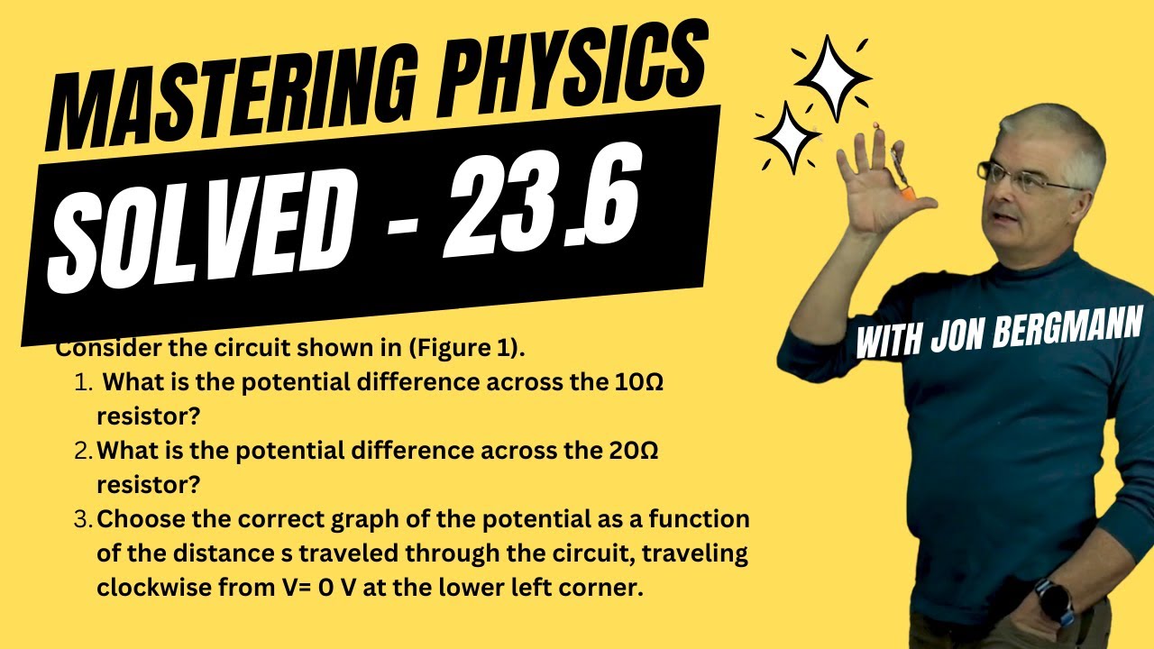
Mastering Physics 23.6 Solved! Consider the circuit shown in (Figure 1). What is the potential
Mastering Physics 23.6 Solved! Consider the circuit shown in (Figure 1). What is the potential
Related image with solved consider the circuit shown in figure figure 1 chegg com
, (Figure | Chegg.com")
, (Figure | Chegg.com")
, (Figure | Chegg.com")
. (Figure | Chegg.com")
, (Figure | Chegg.com")
, (Figure | Chegg.com")
, | Chegg.com")
, (Figure | Chegg.com")
, (Figure | Chegg.com")
 Part A Solve | Chegg.com")
, (Figure | Chegg.com")
 Solve | Chegg.com")
Related image with solved consider the circuit shown in figure figure 1 chegg com
. What is the potential")
. Assume I = 0.88 A. W")


About "Solved Consider The Circuit Shown In Figure Figure 1 Chegg Com"
Comments are closed.