, (Figure | Chegg.com")
Solved Consider The Circuits Shown In (Figure 1), (Figure | Chegg.com
Solved Consider The Circuits Shown In (Figure 1), (Figure | Chegg.com Consider the circuits shown in (figure 1), (figure 2), (figure 3), (figure 4), (figure 5). assume that the op amp is ideal. each of the circuits has negative feedback, so the summing point constraint applies. suppose that r1 = 5 kΩ and r2 = 4 kΩ. your solution’s ready to go!. Given that the initial current is 26 ma, the calculations to find the current i1, i2, and i3 across various resistors are based on applying these rules at different points and loops of the circuit.
, (Figure | Chegg.com")
Solved Consider The Circuits Shown In (Figure 1), (Figure | Chegg.com
Solved Consider The Circuits Shown In (Figure 1), (Figure | Chegg.com . consider the circuit shown in (figure 1). the diode is the led having the characteristic shown in (figure 2). use new york university • ece uy. Step 1/2for figure 1, we can see that it is a non inverting amplifier configuration. the voltage transfer ratio (a (f)) is given by the equation: a (f) = 1 (r2/r1) however, in this case, we have a frequency dependent term in the denominator. To solve parts (g) and (h), we need to understand the circuit configuration. the given resistances are r 1 = 1 2. 0 Ω r1 = 12.0Ω, r 2 = 3. 4 5 Ω r2 = 3.45Ω, and the voltage v = 6. 4 5 v v = 6.45v. we need to find the voltage across a 3. 0 0 Ω 3.00Ω resistor and the current through it. Without the specific diagram (figure 1) mentioned, providing precise mathematical expressions is not feasible. here is the general approach: inductor current il (t): without the figure, solving isn't possible. generally, for an lc circuit: ( i l (t) = \frac {v s} {\omega l}\sin (\omega t) ).
 And (Figure | Chegg.com")
Solved Consider The Circuits Shown In (Figure 1) And (Figure | Chegg.com
Solved Consider The Circuits Shown In (Figure 1) And (Figure | Chegg.com To solve parts (g) and (h), we need to understand the circuit configuration. the given resistances are r 1 = 1 2. 0 Ω r1 = 12.0Ω, r 2 = 3. 4 5 Ω r2 = 3.45Ω, and the voltage v = 6. 4 5 v v = 6.45v. we need to find the voltage across a 3. 0 0 Ω 3.00Ω resistor and the current through it. Without the specific diagram (figure 1) mentioned, providing precise mathematical expressions is not feasible. here is the general approach: inductor current il (t): without the figure, solving isn't possible. generally, for an lc circuit: ( i l (t) = \frac {v s} {\omega l}\sin (\omega t) ). Question: consider the circuits shown in (figure 1). (figure 2) (figure 3), (figure 4). (figure 5). assume that the op amp is ideal. each of the circuits has negative feedback, so the summing point constraint applies. suppose that r1 = 6 kn and r2 = 6 kl. Answer & explanation solved by verified expert rated helpful answered by grandflower8838. Consider the circuit shown in the figure below (figure 1). suppose that r1= 12 Ω, r2 = 26 Ω , r3 = 12 Ω , r4 = 34 Ω , r5 = 5 Ω and r6 = 6 Ω a. determine the value of v2 by using mesh current analysis b. determine the power delivered by the source. Consider the circuit shown in figure 1 below, constructed with an ideal opamp. (note: verification of your answers with ltspice, matlab, etc. is not required for this assignment.).
, (Figure | Chegg.com")
Solved Consider The Circuits Shown In (Figure 1), (Figure | Chegg.com
Solved Consider The Circuits Shown In (Figure 1), (Figure | Chegg.com Question: consider the circuits shown in (figure 1). (figure 2) (figure 3), (figure 4). (figure 5). assume that the op amp is ideal. each of the circuits has negative feedback, so the summing point constraint applies. suppose that r1 = 6 kn and r2 = 6 kl. Answer & explanation solved by verified expert rated helpful answered by grandflower8838. Consider the circuit shown in the figure below (figure 1). suppose that r1= 12 Ω, r2 = 26 Ω , r3 = 12 Ω , r4 = 34 Ω , r5 = 5 Ω and r6 = 6 Ω a. determine the value of v2 by using mesh current analysis b. determine the power delivered by the source. Consider the circuit shown in figure 1 below, constructed with an ideal opamp. (note: verification of your answers with ltspice, matlab, etc. is not required for this assignment.).
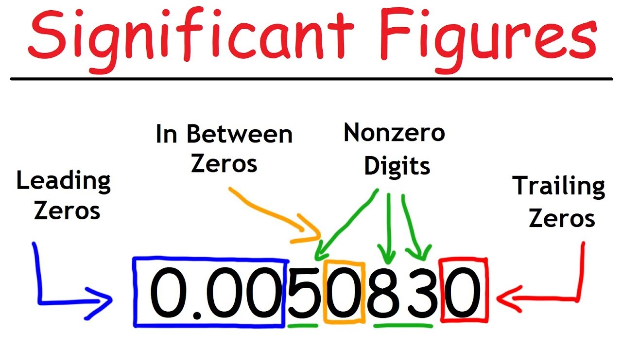
Significant Figures - A Fast Review!
Significant Figures - A Fast Review!
Related image with solved consider the circuits shown in figure 1 figure 2 chegg com
, (Figure | Chegg.com")
, (Figure | Chegg.com")
 And (Figure | Chegg.com")
, (Figure | Chegg.com")
, (Figure | Chegg.com")
, (Figure | Chegg.com")
. (Figure | Chegg.com")
, (Figure | Chegg.com")


, (Figure | Chegg.com")
, (Figure | Chegg.com")
Related image with solved consider the circuits shown in figure 1 figure 2 chegg com

![[Physics] Consider the circuit shown i n the figure, with C 1 = 6 . 5 2 μ F and C 2 = 8 . 5](https://i0.wp.com/ytimg.googleusercontent.com/vi/l0MJXgXX9rM/mqdefault.jpg?resize=91,91 "[Physics] Consider the circuit shown i n the figure, with C 1 = 6 . 5 2 μ F and C 2 = 8 . 5")


About "Solved Consider The Circuits Shown In Figure 1 Figure 2 Chegg Com"
Comments are closed.