, (Figure | Chegg.com")
Solved Consider The Circuits Shown In (Figure 1), (Figure | Chegg.com
Solved Consider The Circuits Shown In (Figure 1), (Figure | Chegg.com Question: consider the circuits shown in| figure 4 . each represents a configuration of leds driven by a voltage or a current source. for the purpose of this problem you can model the led as a resistor. the intensity of the led is proportional to the power dissipated by it. A complex network consisting of a number of parallel branches, where each parallel branch consists of voltage source with series impedance, can be replaced with equivalent circuit consisting of one voltage source in series with equivalent impedance.
, (Figure | Chegg.com")
Solved Consider The Circuits Shown In (Figure 1), (Figure | Chegg.com
Solved Consider The Circuits Shown In (Figure 1), (Figure | Chegg.com To solve parts (g) and (h), we need to understand the circuit configuration. the given resistances are r 1 = 1 2. 0 Ω r1 = 12.0Ω, r 2 = 3. 4 5 Ω r2 = 3.45Ω, and the voltage v = 6. 4 5 v v = 6.45v. we need to find the voltage across a 3. 0 0 Ω 3.00Ω resistor and the current through it. Consider the four circuits shown in figure cq32.4, each consisting of a battery, a switch, a lightbulb, a resistor, and either a capacitor or an inductor. assume the capacitor has a large capacitance and the inductor has a large inductance but no resistance. Identify the nodes in the circuit and assign a reference direction for each branch. write kirchhoff's current law equations for each node, using ohm's law to express currents in terms of voltages and resistances. The discussion revolves around a circuit involving two capacitors, c1 and c2, with given capacitances and a voltage source. initially, c1 is charged to 72 μc when switch s1 is closed.
, (Figure | Chegg.com")
Solved Consider The Circuits Shown In (Figure 1), (Figure | Chegg.com
Solved Consider The Circuits Shown In (Figure 1), (Figure | Chegg.com Identify the nodes in the circuit and assign a reference direction for each branch. write kirchhoff's current law equations for each node, using ohm's law to express currents in terms of voltages and resistances. The discussion revolves around a circuit involving two capacitors, c1 and c2, with given capacitances and a voltage source. initially, c1 is charged to 72 μc when switch s1 is closed. Problem 1. in eac h of the ideal dio de circuits shown below, vin is a 1 khz sinusoid with zero to peak. Our expert help has broken down your problem into an easy to learn solution you can count on. question: consider the circuit shown in figure 4 below, with ideal diodes d1 and d2. figure 4. circuit for problem 4. a) analyze the circuit of figure 4 and sketch voltages v1 (t),v2 (t), and vout (t). clearly label the time/division on your sketches. (a) in the circuit in fig. 4.71, calculate vo and 10 when vs i v. (b) find and io when vs = 10 v. (c) what are vo and 10 when each of the i q resistors is replaced by a 10 q resistor and vs = 10 v?. When one led burns out and becomes an open circuit, the current flowing through that led will be zero. however, the current flowing through the other leds will remain the same.
. (Figure | Chegg.com")
Solved Consider The Circuits Shown In (Figure 1). (Figure | Chegg.com
Solved Consider The Circuits Shown In (Figure 1). (Figure | Chegg.com Problem 1. in eac h of the ideal dio de circuits shown below, vin is a 1 khz sinusoid with zero to peak. Our expert help has broken down your problem into an easy to learn solution you can count on. question: consider the circuit shown in figure 4 below, with ideal diodes d1 and d2. figure 4. circuit for problem 4. a) analyze the circuit of figure 4 and sketch voltages v1 (t),v2 (t), and vout (t). clearly label the time/division on your sketches. (a) in the circuit in fig. 4.71, calculate vo and 10 when vs i v. (b) find and io when vs = 10 v. (c) what are vo and 10 when each of the i q resistors is replaced by a 10 q resistor and vs = 10 v?. When one led burns out and becomes an open circuit, the current flowing through that led will be zero. however, the current flowing through the other leds will remain the same.
. (Figure | Chegg.com")
Solved Consider The Circuits Shown In (Figure 1). (Figure | Chegg.com
Solved Consider The Circuits Shown In (Figure 1). (Figure | Chegg.com (a) in the circuit in fig. 4.71, calculate vo and 10 when vs i v. (b) find and io when vs = 10 v. (c) what are vo and 10 when each of the i q resistors is replaced by a 10 q resistor and vs = 10 v?. When one led burns out and becomes an open circuit, the current flowing through that led will be zero. however, the current flowing through the other leds will remain the same.
, (Figure | Chegg.com")
Solved Consider The Circuits Shown In (Figure 1), (Figure | Chegg.com
Solved Consider The Circuits Shown In (Figure 1), (Figure | Chegg.com
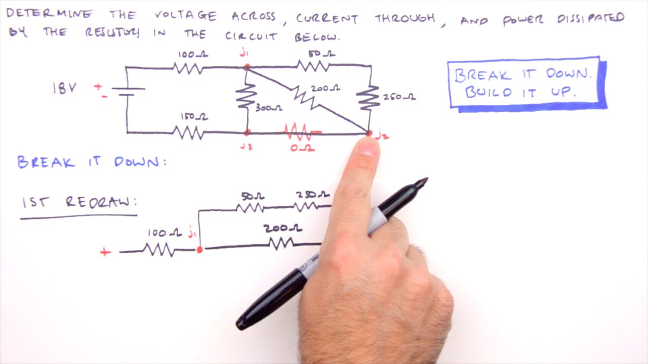
How to Solve Any Series and Parallel Circuit Problem
How to Solve Any Series and Parallel Circuit Problem
Related image with solved consider the circuits shown in figure 4 each chegg com
, (Figure | Chegg.com")
, (Figure | Chegg.com")
, (Figure | Chegg.com")
. (Figure | Chegg.com")
. (Figure | Chegg.com")
, (Figure | Chegg.com")
. (Figure | Chegg.com")
, (Figure | Chegg.com")
, (Figure | Chegg.com")
, (Figure | Chegg.com")
, (Figure | Chegg.com")
, (Figure | Chegg.com")
Related image with solved consider the circuits shown in figure 4 each chegg com


About "Solved Consider The Circuits Shown In Figure 4 Each Chegg Com"
Comments are closed.