
Solved Problem \#4: For The Circuit In Figure 4, Use The | Chegg.com
Solved Problem \#4: For The Circuit In Figure 4, Use The | Chegg.com Our expert help has broken down your problem into an easy to learn solution you can count on. there are 3 steps to solve this one. consider the node labeled v 1 not the question you’re looking for? post any question and get expert help quickly. Op amp circuit problem. b4. for the ideal op amp circuit shown in figure 4, determine "io" and voltage curtin university • electrical.

Solved Figure 4: Circuit For Problem 4 Problem 4: Consider | Chegg.com
Solved Figure 4: Circuit For Problem 4 Problem 4: Consider | Chegg.com 4 using fig. 4, design a problem to help other students better understand linearity. although there are many ways to work this problem, this is an example based on the same kind. Now, with expert verified solutions from fundamentals of electric circuits 4th edition, you’ll learn how to solve your toughest homework problems. our resource for fundamentals of electric circuits includes answers to chapter exercises, as well as detailed information to walk you through the process step by step. Electric circuit analysis chapter 4 problem with solution | ece 2004, assignments for electrical circuit analysis. The discussion revolves around a circuit involving two capacitors, c1 and c2, with given capacitances and a voltage source. initially, c1 is charged to 72 μc when switch s1 is closed.

Solved Figure 4: Circuit For Problem 4 Problem 4: Consider | Chegg.com
Solved Figure 4: Circuit For Problem 4 Problem 4: Consider | Chegg.com Electric circuit analysis chapter 4 problem with solution | ece 2004, assignments for electrical circuit analysis. The discussion revolves around a circuit involving two capacitors, c1 and c2, with given capacitances and a voltage source. initially, c1 is charged to 72 μc when switch s1 is closed. Your solution’s ready to go! our expert help has broken down your problem into an easy to learn solution you can count on. there are 3 steps to solve this one. not the question you’re looking for? post any question and get expert help quickly. Answer & explanation solved by verified expert answered by ministeruniverse11432. Simplifying the circuit and writing the mesh equations. the below sketch shows how this procedure is achieved. the first step we are going to take in mesh analysis is to assign a clockwise direction for the current of each internal closed loop at the network. Problem 1. in eac h of the ideal dio de circuits shown below, vin is a 1 khz sinusoid with zero to peak.

Solved Figure 4: Circuit For Problem 4 Problem 4: Consider | Chegg.com
Solved Figure 4: Circuit For Problem 4 Problem 4: Consider | Chegg.com Your solution’s ready to go! our expert help has broken down your problem into an easy to learn solution you can count on. there are 3 steps to solve this one. not the question you’re looking for? post any question and get expert help quickly. Answer & explanation solved by verified expert answered by ministeruniverse11432. Simplifying the circuit and writing the mesh equations. the below sketch shows how this procedure is achieved. the first step we are going to take in mesh analysis is to assign a clockwise direction for the current of each internal closed loop at the network. Problem 1. in eac h of the ideal dio de circuits shown below, vin is a 1 khz sinusoid with zero to peak.

Solved Figure 4: Circuit For Problem 4 Problem 4: The | Chegg.com
Solved Figure 4: Circuit For Problem 4 Problem 4: The | Chegg.com Simplifying the circuit and writing the mesh equations. the below sketch shows how this procedure is achieved. the first step we are going to take in mesh analysis is to assign a clockwise direction for the current of each internal closed loop at the network. Problem 1. in eac h of the ideal dio de circuits shown below, vin is a 1 khz sinusoid with zero to peak.

Solved Figure 3: Circuit For Problem 4Figure 3: Circuit For | Chegg.com
Solved Figure 3: Circuit For Problem 4Figure 3: Circuit For | Chegg.com
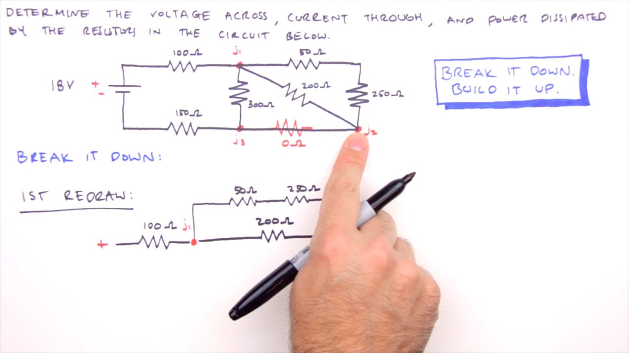
How to Solve Any Series and Parallel Circuit Problem
How to Solve Any Series and Parallel Circuit Problem
Related image with solved figure 4 circuit for problem 4 problem 4 consider chegg com


 Consider The Circuit Shown In | Chegg.com")

Related image with solved figure 4 circuit for problem 4 problem 4 consider chegg com


PART-1")

About "Solved Figure 4 Circuit For Problem 4 Problem 4 Consider Chegg Com"
Comments are closed.