
Solved Consider The Circuit Shown In The Diagram Belo - Vrogue.co
Solved Consider The Circuit Shown In The Diagram Belo - Vrogue.co Your solution’s ready to go! our expert help has broken down your problem into an easy to learn solution you can count on. see answer. To solve parts (g) and (h), we need to understand the circuit configuration. the given resistances are r 1 = 1 2. 0 Ω r1 = 12.0Ω, r 2 = 3. 4 5 Ω r2 = 3.45Ω, and the voltage v = 6. 4 5 v v = 6.45v. we need to find the voltage across a 3. 0 0 Ω 3.00Ω resistor and the current through it.

Solved Consider The Circuit Shown In The Figure Below. | Chegg.com
Solved Consider The Circuit Shown In The Figure Below. | Chegg.com Consider the circuit shown in the figure below. [15 points] (a) obtain an expression for the apparent power, s, by the sending end voltage source, your answer should only contain vs, vr, δ, x, and b. [5 points] (b) obtain an expression for the real power generated by the sending end voltage source, vs. We observe that, once we get the value of the collector current of the 2nd transistor, we can evaluate vc2. the circuit is redrawn as: applying kvl through. Answer & explanation solved by verified expert rated helpful answered by thulasibukkana2145. Your solution’s ready to go! our expert help has broken down your problem into an easy to learn solution you can count on. see answer.

Solved 2. Consider The Circuit Shown In Figure 2 Below. | Chegg.com
Solved 2. Consider The Circuit Shown In Figure 2 Below. | Chegg.com Answer & explanation solved by verified expert rated helpful answered by thulasibukkana2145. Your solution’s ready to go! our expert help has broken down your problem into an easy to learn solution you can count on. see answer. The voltage across each component in a series rlc circuit is given by ohm's law. for the resistor, it's v r = i*r, for the inductor, it's v l = l*di/dt, and for the capacitor, it's v c = q/c. Problem 12: consider the circuit shown in the figure below, where r1=9.00 Ω, r2=6.00 Ω, and ε=12.0 v. find the electric current in resistor r1. (a) 0.928 a (b) 1.56 a (c) 2.25 a (d) 0.732 a (e) 0.325 a. The 4 q resistor is short circuited so that the resulting circuit is as shown in fig. (a). 12 v 12 (a) (b) since the current through an inductor cannot change abluptly, when t > 0, the voltage source is cut off and we have the rl circuit in fig. (b). 0.5 hence, chapter 7, problem 19. There are 3 steps to solve this one. consider the circuit shown below. not the question you’re looking for? post any question and get expert help quickly. answer to consider the circuit shown below.

Solved Consider The Circuit Shown In Figure 1 Assume - Vrogue.co
Solved Consider The Circuit Shown In Figure 1 Assume - Vrogue.co The voltage across each component in a series rlc circuit is given by ohm's law. for the resistor, it's v r = i*r, for the inductor, it's v l = l*di/dt, and for the capacitor, it's v c = q/c. Problem 12: consider the circuit shown in the figure below, where r1=9.00 Ω, r2=6.00 Ω, and ε=12.0 v. find the electric current in resistor r1. (a) 0.928 a (b) 1.56 a (c) 2.25 a (d) 0.732 a (e) 0.325 a. The 4 q resistor is short circuited so that the resulting circuit is as shown in fig. (a). 12 v 12 (a) (b) since the current through an inductor cannot change abluptly, when t > 0, the voltage source is cut off and we have the rl circuit in fig. (b). 0.5 hence, chapter 7, problem 19. There are 3 steps to solve this one. consider the circuit shown below. not the question you’re looking for? post any question and get expert help quickly. answer to consider the circuit shown below.
![[Solved]: Consider The Circuit Shown In The Figure Below.](https://i0.wp.com/media.cheggcdn.com/study/773/773a718c-53a6-4914-84c6-69e726f56031/image?resize=650,400 "[Solved]: Consider The Circuit Shown In The Figure Below.")
[Solved]: Consider The Circuit Shown In The Figure Below.
[Solved]: Consider The Circuit Shown In The Figure Below. The 4 q resistor is short circuited so that the resulting circuit is as shown in fig. (a). 12 v 12 (a) (b) since the current through an inductor cannot change abluptly, when t > 0, the voltage source is cut off and we have the rl circuit in fig. (b). 0.5 hence, chapter 7, problem 19. There are 3 steps to solve this one. consider the circuit shown below. not the question you’re looking for? post any question and get expert help quickly. answer to consider the circuit shown below.

Solved Consider The Circuit Shown Below. The Switch In The | Chegg.com
Solved Consider The Circuit Shown Below. The Switch In The | Chegg.com
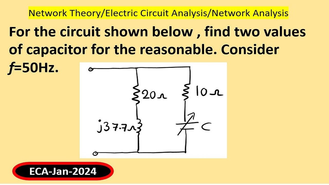
For the circuit shown below , find two values of capacitor for the reasonable. Consider f=50Hz.
For the circuit shown below , find two values of capacitor for the reasonable. Consider f=50Hz.
Related image with solved page 2 q2 consider the circuit shown below r s chegg com


![[Solved]: Consider The Circuit Shown In The Figure Below.](https://i0.wp.com/media.cheggcdn.com/study/773/773a718c-53a6-4914-84c6-69e726f56031/image?resize=91,91 "[Solved]: Consider The Circuit Shown In The Figure Below.")

![[Solved] Q2. (b) Consider The Circuit Of Figure.2b Shown Below: 10 0 RI 100... | Course Hero](https://i0.wp.com/www.coursehero.com/qa/attachment/35711866/?resize=91,91 "[Solved] Q2. (b) Consider The Circuit Of Figure.2b Shown Below: 10 0 RI 100... | Course Hero")


Related image with solved page 2 q2 consider the circuit shown below r s chegg com


About "Solved Page 2 Q2 Consider The Circuit Shown Below R S Chegg Com"
Comments are closed.