 In The Following Figure (Figure 3), | Chegg.com")
Solved Question 3(a) In The Following Figure (Figure 3), | Chegg.com
Solved Question 3(a) In The Following Figure (Figure 3), | Chegg.com Our expert help has broken down your problem into an easy to learn solution you can count on. question: 3. consider the circuit shown in figure 3 . (a) use source transformation to replace the current sources with their equivalent voltage sources. Consider a silicon sample maintained at 300k under equilibrium conditions, uniformly doped with 1*1016 cm 3 phosphorus atoms. the surface region of the sample is additionally doped uniformly with 5*1016 cm 3 boron atoms, to a depth of 1 microm, as shown in the figure below.

Solved Problem 3: For The Following Figure As Being | Chegg.com
Solved Problem 3: For The Following Figure As Being | Chegg.com At chegg we understand how frustrating it can be when you’re stuck on homework questions, and we’re here to help. our extensive question and answer board features hundreds of experts waiting to provide answers to your questions, no matter what the subject. Question 4.1 (3 points) a simple cantilever is subject to the loading conditions shown below. Consider a circuit shown below in which r 1 and r 2 are two resistance, v 1, v 2 are two voltage source which causes current (i) flow in the loop. the sign of voltage drop across the passive element is such a way that the current entering from the positive terminal. note: kvl deals with the conservation of energy. Answer the question in the picture. a vector whose length is proportional to the maximum value of the variable it represents. it rotates counterclockwise at an angular speed equal to the angular frequency associated with the variable.

Solved Figure 2 Figure 3 | Chegg.com
Solved Figure 2 Figure 3 | Chegg.com Consider a circuit shown below in which r 1 and r 2 are two resistance, v 1, v 2 are two voltage source which causes current (i) flow in the loop. the sign of voltage drop across the passive element is such a way that the current entering from the positive terminal. note: kvl deals with the conservation of energy. Answer the question in the picture. a vector whose length is proportional to the maximum value of the variable it represents. it rotates counterclockwise at an angular speed equal to the angular frequency associated with the variable. The document contains solved problems related to semiconductor diodes. it provides the circuit diagrams, parameters, equations and step by step solutions for each problem. . v part a consider the circuit shown in (figure 1). suppose that v1 = 8 v and v2 = 3 v. use the mesh current answered step by step solved by verified expert university of washington. For the circuit shown in figure 3, determine and sketch its voltage transfer characteristic. assume diodes are ideal. 10 v 10 k 10 k 10 k 10 v. your solution’s ready to go! our expert help has broken down your problem into an easy to learn solution you can count on. Search our library of 100m curated solutions that break down your toughest questions. ask one of our real, verified subject matter experts for extra support on complex concepts. test your knowledge anytime with practice questions. create flashcards from your questions to quiz yourself.
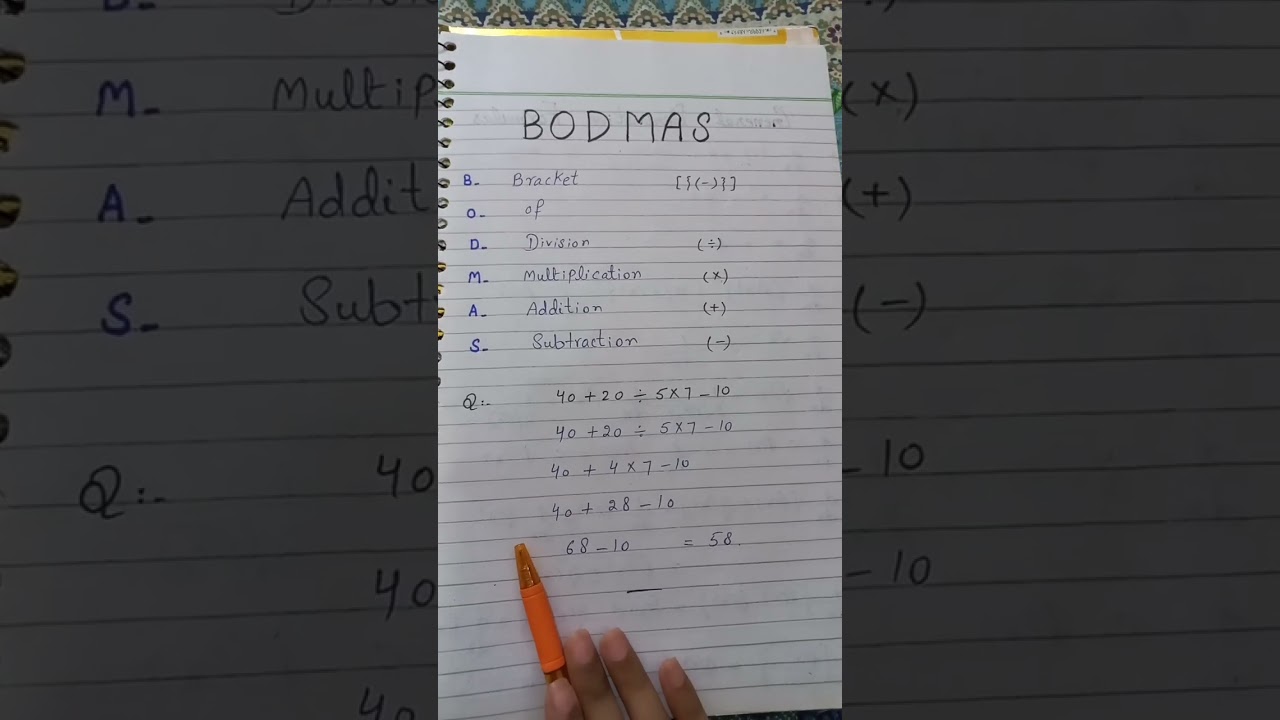
BODMAS RULE
BODMAS RULE
Related image with solved question 3a in the following figure figure 3 chegg com
 In The Following Figure (Figure 3), | Chegg.com")


 | Chegg.com")
 | Chegg.com")

Related image with solved question 3a in the following figure figure 3 chegg com


About "Solved Question 3a In The Following Figure Figure 3 Chegg Com"
Comments are closed.