
Figure 4 Figure 4 | Chegg.com
Figure 4 Figure 4 | Chegg.com Our expert help has broken down your problem into an easy to learn solution you can count on. question: question 4 from the diagrams above, figure 2 shows which of the following?. The graph below shows the market for milk where the government imposes a price floor of $5. fill in the blanks below with the correct terms and numbers up to two decimal places.

Solved Figure 2 Of 4 Figure | Chegg.com
Solved Figure 2 Of 4 Figure | Chegg.com Op amps solved problems free download as pdf file (.pdf), text file (.txt) or read online for free. the document contains solutions to 37 problems from chapter 4 on operational amplifiers in irwin's basic engineering circuit analysis textbook. This document discusses block diagram reduction techniques. it provides steps to simplify a block diagram and determine the closed loop transfer function. Figure 3 74 shows a closed loop system with a ref erence input and disturbance input. obtain the expression for the output c(s) when both the reference input and dis turbance input are present. Solved problems on zener diode q1. for the circuit shown in fig.1 (i), find : (i) the output voltage (ii) the voltage drop across series resistance (iii) the current through zener.

Solved Figure 2 Of 4 Figure | Chegg.com
Solved Figure 2 Of 4 Figure | Chegg.com Figure 3 74 shows a closed loop system with a ref erence input and disturbance input. obtain the expression for the output c(s) when both the reference input and dis turbance input are present. Solved problems on zener diode q1. for the circuit shown in fig.1 (i), find : (i) the output voltage (ii) the voltage drop across series resistance (iii) the current through zener. Answer to 2. for the circuit shown in figure 2, find io/is. It provides the circuit diagrams, parameters, equations and step by step solutions for each problem. problem 2.4 involves analyzing the current in a circuit with multiple diodes and a square wave voltage source. Ask any question and get an answer from our subject experts in as little as 2 hours. Calculate the value of series resistance r for the circuit in fig. 5 to regulate the voltage across a variable load resistor. the series resistance r value is 200 Ω. determine the regulated output voltage and the value of series resistance r for the circuit in fig. 6 using two zener diodes.

Solved Figure 2 Of 4 Figure | Chegg.com
Solved Figure 2 Of 4 Figure | Chegg.com Answer to 2. for the circuit shown in figure 2, find io/is. It provides the circuit diagrams, parameters, equations and step by step solutions for each problem. problem 2.4 involves analyzing the current in a circuit with multiple diodes and a square wave voltage source. Ask any question and get an answer from our subject experts in as little as 2 hours. Calculate the value of series resistance r for the circuit in fig. 5 to regulate the voltage across a variable load resistor. the series resistance r value is 200 Ω. determine the regulated output voltage and the value of series resistance r for the circuit in fig. 6 using two zener diodes.
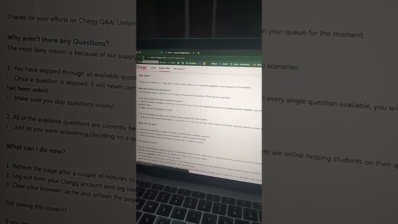
Chegg Down? No Question Available at 11:20 pm? Here's What You Can Do!
Chegg Down? No Question Available at 11:20 pm? Here's What You Can Do!
Related image with solved question 4 from the diagrams above figure 2 shows chegg com


Related image with solved question 4 from the diagrams above figure 2 shows chegg com


About "Solved Question 4 From The Diagrams Above Figure 2 Shows Chegg Com"
Comments are closed.