Transformer Rectifier Circuit Full Wave Bridge Rectifier Circuit With Capacitor Transformer

Full Wave Bridge Rectifier Circuit Diagram - Circuit Diagram
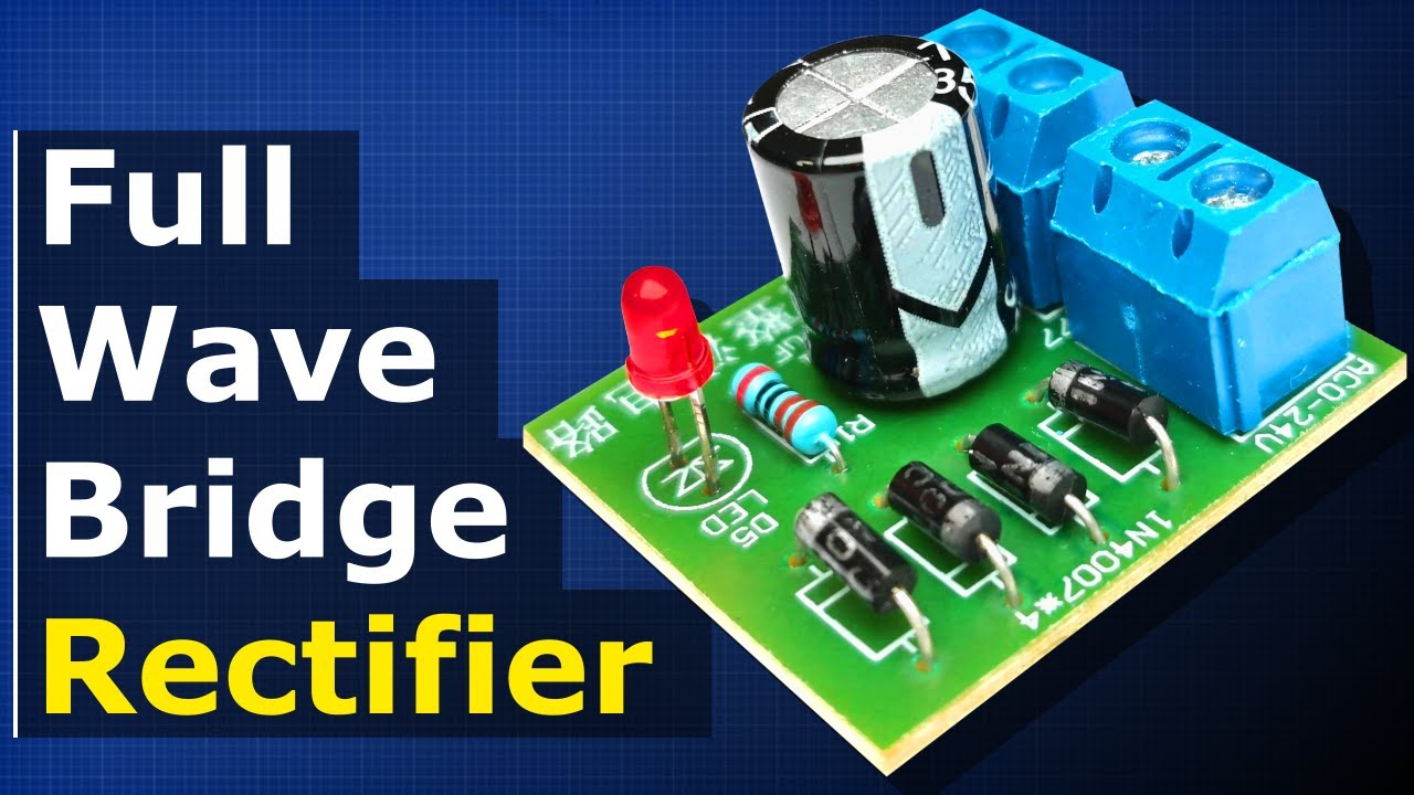
Full Wave Bridge Rectifier Circuit Diagram - Circuit Diagram The main advantages of a full wave bridge rectifier is that it has a smaller ac ripple value for a given load and a smaller reservoir or smoothing capacitor than an equivalent half wave rectifier. This rectifier circuit produces the same output waveform as the full wave rectifier circuit. the main advantage of the bridge rectifier is that the expensive center tapped transformer is not used in this design, a normal transformer is used in place of a center tapped transformer.

Full Wave Bridge Rectifier Circuit With Capacitor Filter - Circuit Diagram
Full Wave Bridge Rectifier Circuit With Capacitor Filter - Circuit Diagram In this tutorial, we are going to make a “full wave bridge rectifier circuit”. many electronic circuits require a rectified dc power supply, for powering the various electronic basic components from available ac mains supply. Full wave bridge rectifier circuit diagram is widely used in ac to dc converter and dc circuit designs, this full wave rectifier called as bridge rectifier due to it shape. it contains four diodes arranged in a bridge format and an ordinary step down transformer. In this hands on semiconductor experiment, build an improved full wave rectifier with output filtering and learn about capacitive filtering in ac to dc power converters. In this article, we will discuss the working of center tapped and bridge type full wave rectifiers. the full wave rectifier converts ac to dc.

Wave Bridge Rectifier Circuit Diagram
Wave Bridge Rectifier Circuit Diagram In this hands on semiconductor experiment, build an improved full wave rectifier with output filtering and learn about capacitive filtering in ac to dc power converters. In this article, we will discuss the working of center tapped and bridge type full wave rectifiers. the full wave rectifier converts ac to dc. In full wave bridge rectifier, an ordinary transformer is used in place of a center tapped transformer. the circuit form a bridge connecting the four diodes d1, d2, d3 and d4. The full wave rectifier delivers twice the voltage and quadruple power to the load as compared to the half wave rectifier. it makes the full wave rectifier more efficient and for the same voltage power supply a smaller transformer can be utilized compared to using a half wave rectifier. This post includes full wave bridge rectifier circuit diagram, working and applications. here, diodes are arranged in the form of a bridge.
Full Wave Bridge Rectifier + Capacitor filters + half wave rectifier
Full Wave Bridge Rectifier + Capacitor filters + half wave rectifier
Related image with transformer rectifier circuit full wave bridge rectifier circuit with capacitor transformer


")


Related image with transformer rectifier circuit full wave bridge rectifier circuit with capacitor transformer


About "Transformer Rectifier Circuit Full Wave Bridge Rectifier Circuit With Capacitor Transformer"
Comments are closed.